Rockwell Automation 1606-XLSRED80 DC Power Supply Redundancy Module User Manual
Page 4
1606-XLSRED Decoupling Module Instruction Manual / Bedienungsanleitung Entkopplungsmodul
1606-XLERED Redundancy Module Instruction Manual / Bedienungsanleitung Redundanzmodul
Installation
Use DIN-rails according to EN 60715 or EN 50022 with a height of 7.5 or 15mm.
Use only with the following mounting orientations:
1606-XLSRED, 1606-XLERED, 1606-XLSRED40: input terminals on top and output terminal on
the bottom
1606-XLSRED80: input terminals on the bottom and output terminal on top
For other orientations see datasheet. Do not obstruct air flow as the unit is convection cooled.
Ventilation grid must be kept free of any obstructions.
Keep the following installation clearances:
40mm on top, 20mm on the bottom,
5mm on the left and right sides are recommended when the redundancy module is loaded
permanently with more than 50% of the rated output current. Increase the side clearance to
15mm in case the adjacent device is a heat source (e.g. another power supply).
Installation
Geeignet für DIN-Schienen gemäß EN 60715 oder EN 50022 mit einer Höhe von 7,5 oder 15mm.
Folgende Standard- Einbaulagen sind zu beachten:
1606-XLSRED, 1606-XLERED, 1606-XLSRED40: Eingangsklemmen oben, Ausgangsklemme
unten
1606-XLSRED80: Eingangsklemmen unten, Ausgangsklemme oben
Für andere Einbaulagen siehe Datenblatt. Luftzirkulation nicht behindern! Das Gerät ist für
Konvektionskühlung ausgelegt. Es ist für ungehinderte Luftzirkulation zu sorgen.
Folgende Einbauabstände sind einzuhalten:
Oben: 40mm, unten 20mm vom Gerät
Links und rechts sind 5mm empfohlen, wenn das Redundanzmodul dauerhaft mit mehr als
50% des Nennausgangsstroms belastet ist. Der Abstand muss auf 15mm erhöht werden,
wenn das benachbarte Gerät eine Wärmequelle ist (z.B. eine weitere Stromversorgung).
Terminals and Wiring
Use appropriate copper cables that are designed for minimum operating temperatures of:
60°C for ambient up to 45°C and 75°C for ambient up to 60°C and 90°C for ambient up to 70°C
minimum. Follow national installation codes and regulations! Ensure that all strands of a stranded
wire enter the terminal connection! Up to two stranded wires with the same cross section are
permitted in one connection point. Ferrules are allowed, but not required. In order to fulfill shock
and vibration requirements of GL, unused terminal must be closed. The external circuitry of all
terminals (including signalling contacts) must meet the safety requirements stipulated by
IEC/EN/UL 60950-1: SELV.
1606-XLSRED Input and output terminals (spring-clamp type):
Solid wire / stranded wire / AWG
0.5-6mm
2
/ 0.5-4mm
2
/ 20-10 AWG
Wire stripping length
10mm / 0.4inch
1606-XLERED Input and output terminals (screw type):
Solid wire / stranded wire / AWG
0.5-6mm
2
/ 0.5-4mm
2
/ 20-10 AWG
Wire stripping length / tightening torque
7mm / 0.28inch / 0.8Nm / 7lb.inch
Signal
terminals (plug connector, screw type):
Solid wire / stranded wire / AWG
0.2-1.5mm
2
/ 0.2-1.5mm
2
/ 22-14 AWG
Wire stripping length / tightening torque
6mm / 0.25inch / 0.4Nm / 3.5lb.inch
1606-XLSRED40
Input terminals (screw type):
Solid wire / stranded wire / AWG
0.5-6mm
2
/ 0.5-4mm
2
/ 20-10 AWG
Wire stripping length / tightening torque
7mm / 0.28inch / 0.8Nm / 7lb.inch
Output
terminals (screw type):
Solid wire / stranded wire / AWG
0.5-16mm
2
/ 0.5-10mm
2
/ 22-8 AWG
Wire stripping length / tightening torque
12mm / 0.5inch / 1.2Nm / 10.6lb.inch
1606-XLSRED80 Input
terminals (screw type):
Solid wire / stranded wire / AWG
0.5-16mm
2
/ 0.5-10mm
2
/ 22-8 AWG
Wire stripping length / tightening torque
12mm / 0.5inch / 1.2Nm / 10.6lb.inch
Output
terminals (screw type):
Solid wire / stranded wire / AWG
0.5-35mm
2
/ 0.5-35mm
2
/ 20-2 AWG
Wire stripping length / tightening torque
18mm / 0.7inch / 2.5Nm / 22lb.inch
Anschlussklemmen und Verdrahtung
Verwenden Sie Kupferkabel, die für folgende Mindest- Betriebstemperatur zugelassen sind:
60°C bei Umgebungstemperaturen bis zu 45°C und 75°C bei Umgebungstemperaturen bis zu
60°C und 90°C bei Umgebungstemperaturen bis zu 70°C. Beachten Sie nationale Bestimmungen
und Installationsvorschriften! Stellen Sie sicher, dass keine einzelnen Drähte von Litzen abstehen.
Bis zu zwei Leiter mit gleichem Querschnitt sind in einem Anschlusspunkt erlaubt. Aderendhülsen
sind erlaubt, aber nicht erforderlich. Nichtbenutzte Klemmen zudrehen, um die GL Schock- und
Vibrationsanforderungen zu erfüllen. Die externe Beschaltung aller Klemmen (einschließlich
Signalklemmen) muss den Anforderungen an SELV Kreisen nach IEC/EN/UL 60950-1 genügen.
1606-XLSRED Eingang- und Ausgangsklemmen (Federkraftklemme):
Starrdraht / Litze / AWG
0,5-6mm
2
/ 0,5-4mm
2
/ 20-10 AWG
Abisolierlänge
10mm
/
0,4inch
1606-XLERED Eingang- und Ausgangsklemmen (Schraubklemme):
Starrdraht / Litze / AWG
0,5-6mm
2
/ 0,5-4mm
2
/ 20-10 AWG
Abisolierlänge / Anzugsdrehmoment
7mm / 0,28inch / 0,8Nm / 7lb.inch
Signalklemmen (Steckverbinder mit Schraubklemme):
Starrdraht / Litze / AWG
0,2-1,5mm
2
/ 0,2-1,5mm
2
/ 22-14 AWG
Abisolierlänge / Anzugsdrehmoment
6mm / 0,25inch / 0,4Nm / 3,5lb.inch
1606-XLSRED40
Eingangsklemmen (Schraubklemme):
Starrdraht / Litze / AWG
0,5-6mm
2
/ 0,5-4mm
2
/ 20-10 AWG
Abisolierlänge / Anzugsdrehmoment
7mm / 0,28inch / 0,8Nm / 7lb.inch
Ausgangsklemmen (Schraubklemme):
Starrdraht / Litze / AWG
0,5-16mm
2
/ 0,5-10mm
2
/ 22-8 AWG
Abisolierlänge / Anzugsdrehmoment
12mm / 0,5inch / 1,2Nm / 10,6lb.inch
1606-XLSRED80 Eingangsklemmen (Schraubklemme):
Starrdraht / Litze / AWG
0,5-16mm
2
/ 0,5-10mm
2
/ 22-8 AWG
Abisolierlänge / Anzugsdrehmoment
12mm / 0,5inch / 1,2Nm / 10,6lb.inch
Ausgangsklemmen (Schraubklemme):
Starrdraht / Litze / AWG
0,5-35mm
2
/ 0,5-35mm
2
/ 20-2 AWG
Abisolierlänge / Anzugsdrehmoment
18mm / 0,7inch / 2,5Nm / 22lb.inch
EMC Electromagnetic Compatibility
The devices are suitable for applications in industrial environment as well as in residential,
commercial and light industry environment without any restrictions. These devices comply with
FCC Part 15 rules.
CE mark is in conformance with EMC directive 2004/108/EC as well as the low-voltage directive
(LVD) 2006/95/EC.
EMC Immunity: EN 61000-6-1, EN 61000-6-2
EMC Emission EN 61000-6-3, EN 61000-6-4, FCC Part 15 Class B
EMV Elektromagnetische Verträglichkeit
Diese Geräte erfüllen die Anforderungen für Anwendungen in industrieller Umgebung und für den
Wohn-, Geschäfts- und Gewerbebereich ohne Einschränkungen. Die Geräte erfüllen die
Anforderungen der FCC Teil 15.
Das CE Zeichen ist angebracht und erklärt die Erfüllung der EMV Richtlinie 2004/108/EG wie
auch der Niederspannungsrichtlinie 2006/95/EG.
Störfestigkeit: EN 61000-6-1, EN 61000-6-2
Störaussendung: EN 61000-6-3, EN 61000-6-4, FCC Part 15 Klasse B
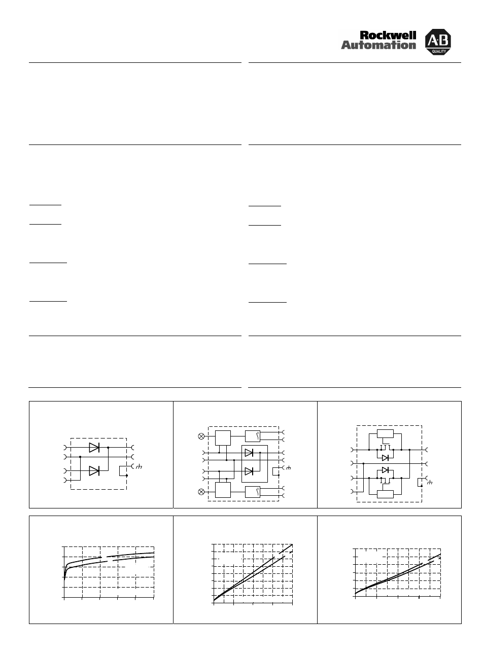
Fig. 3 / Bild 3
1606-XLSRED: Functional Diagram / Funktionsschaltbild
Fig. 4 / Bild 4
1606-XLERED: Functional Diagram / Funktionsschaltbild
Fig. 5 / Bild 5
1606-XLSRED40, 1606-XLSRED80: Functional Diagram /
Funktionsschaltbild
+
-
+
-
+
-
Input 1
Input 2
Output
Chassis
Ground
+
-
+
-
+
-
Alarm
Relay
Input
Voltage
Monitor
Input 1
Alarm
contact
Alarm
Relay
Input
Voltage
Monitor
Input 2
Alarm
contact
Input 1
ok
Input 2
ok
Input 1
Input 2
Output
Chassis
Ground
+
-
+
-
+
-
Input 1
control
control
Input 2
Chassis
Ground
Output
Fig. 6 / Bild 6
1606-XLSRED/1606-XLERED: Voltage Drop / Spannungsabfall
Fig. 7 / Bild 7
1606-XLSRED40: Voltage Drop / Spannungsabfall
Fig. 8 / Bild 8
1606-XLSRED80: Voltage Drop / Spannungsabfall
Input to Output Voltage Drop, typ.
0A
5A
10A
20A
200mV
400mV
600mV
800mV
1000mV
25A
15A
Input, Output Current
0mV
Output:
2x5A
2x2.5A
Input:
2x10A
2x7.5A
0A
2x12.5A
A... 25°C
B... 60°C
A
B
Input to Output Voltage Drop, typ.
0mV
10A
30A
20mV
40mV
60mV
80mV
100mV
120mV
40A
20A
Output:
A... 25°C
B... 60°C
2x10A
2x5A
Input / Output Current
Input:
2x20A
2x15A
0
0
140mV
160mV
A
B
Input to Output Voltage Drop, typ.
0mV
20A
60A
20mV
40mV
60mV
80mV
100mV
120mV
80A
40A
Output:
A... 25°C
B... 60°C
2x20A
2x10A
Input / Output Current
Input:
2x40A
2x30A
0
0
A
B