B frame & up drives – Rockwell Automation 1336S PLUS II Analog Interface Inst. User Manual
Page 3
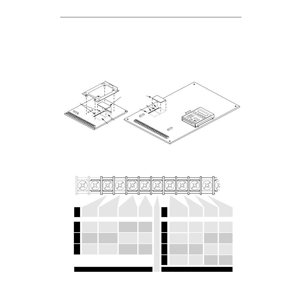
1336 PLUS II Analog Interface Option Board Installation
3
B Frame & Up Drives
A. Locate the appropriate slot for installation. Remove any
jumpers (from J9 or J10) present for that slot.
B. Carefully align the option board (connector side down)
mounting holes with the standoffs. Press the board into posi-
tion until the mounting posts lock onto the board.
C. Apply power and verify board presence by checking [Slot A
Option] or [Slot B Option] in the Analog I/O Group. The
board type should be indicated in the appropriate parameter.
The terminal designations of TB2 change based on the option
board(s) installed – refer to the diagram below.
Frames A1 - A4
Frames B & Up
JOG
ESC
SEL
ANALOG I/O
SLO
T B
8
6
4
2
7
5
3
1
J10
ANALOG I/O
SLO
T A
8
6
4
2
7
5
3
1
J9
Analog Option Board
ANALOG I/O
SLO
T B
8
6
4
2
7
5
3
1
J10
ANALOG I/O
SLO
T A
8
6
7
5
3
1
J9
J9, J10
J9, J10
Slot B
Slot B
Slot A
Slot A
1
TE
TE
Signal
Common
Only Present
on B Frame
& Up Drives
2
3
4
5
6
9
8
7
Isolated
Input 0 (–)
10V or 20mA
Isolated
Input 0 (–)
±
10V,
±
20mA
Isolated
Input 0 (–)
±
10V,
±
20mA
Isolated
Input 0 (+)
10V or 20mA
Isolated
Input 0 (+)
±
10V,
±
20mA
Isolated
Input 0 (+)
±
10V,
±
20mA
LA2
LA6
LA7
Analog I/O Option Slot A
Analog I/O Option Slot B
Isolated
Input 1 (+)
10V or 20mA
Thermistor
Isolated
Input (+)
Isolated
Input 1 (+)
10V or 20mA
Isolated
Input 1 (–)
10V or 20mA
Thermistor
Isolated
Input (–)
Isolated
Input 1 (–)
10V or 20mA
Pot.
Reference
+5V
1
Single-Ended
Input 0
Pot., 10V or 20mA
Single-Ended
Input 1
Pot., 10V or 20mA
Signal
Common
S
i
g
n
a
l
C
o
m
m
o
n
Std.
LA1
LA3
LA4
LA5
Std.
or (select 1)
or (select 1)
Single-Ended
Input 2
2
Pot., 10V or 20mA
Isolated
Output 0 (+)
10V or 20mA
Isolated
Input 2 (+)
10V or 20mA
Single-Ended
Output 0
10V or 20mA
Single-Ended
Output 0
10V or 20mA
Isolated
Output 0 (–)
10V or 20mA
Isolated
Input 2 (–)
10V or 20mA
Non-Isolated
250 kHz
Pulse Output
Single-Ended
Output 1
20mA Only
Isolated
Output 1 (+)
10V or 20mA
Isolated
Output 1 (+)
10V or 20mA
Isolated
250 kHz
Pulse In (+)
0-20mA
Output
Return
Isolated
Output 1 (–)
10V or 20mA
Isolated
Output 1 (–)
10V or 20mA
Isolated
250 kHz
Pulse In (–)
Signal
Common
Single Ended
Output 1
0-10V Only
Single Ended
Output 0
0-10V Only
Single-Ended
Input 2
Pot., 10V or 20mA
1
If an Option Board is installed in Slot A, the +5V pot. reference will not be
available. If a 5V source is required, it must be user supplied.
2
Standard Analog Input 2 is maintained at this terminal – configure with J11.