A1 - a4 frame drives – Rockwell Automation 1336S PLUS II Analog Interface Inst. User Manual
Page 2
2
1336 PLUS II Analog Interface Option Board Installation
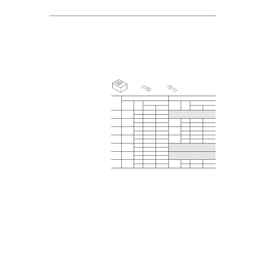
3. Set the DIP switches for desired configuration.
Each board will have one or two DIP switches depending on the
option selected. The first function (input or output) is configured
with the S1 DIP switch – the second function is configured with
S51. Using the table below, set the switch(es) for correct operation.
Important:
Due to different switch manufacturers, the individual
switches will be designated “A or 1” and “B or 2.” In
addition, switch positions will be indicated as “Off or
0” and “On or 1.”
S1 and S51 Configuration Settings
4. Install board using appropriate instructions for your drive.
A1 - A4 Frame Drives
A. Remove the HIM (or other option). Remove the four screws
securing the HIM mounting cradle.
B. Using the following figure, locate the appropriate slot for
installation. Remove any jumpers (from J9 or J10) present for
that slot.
C. Carefully align the option board (connector side down)
mounting holes with the standoffs. Press the board into posi-
tion until the mounting posts lock onto the board.
D. Replace the mounting cradle and any devices previously
removed. Replace drive cover.
E. Apply power and verify board presence by checking [Slot A
Option] or [Slot B Option] in the Analog I/O Group. The
board type should be indicated in the appropriate parameter.
Option
DIP Switch S1
DIP Switch S51
Function Mode
Switch Setting
Function Mode
Switch Setting
A/1
B/2
A/1
B/2
LA1
Output 0 10V
Off/“0”
Off/“0”
Configure Standard Analog Input 2 with J11.
Refer to User Manual for further information.
20mA On/“1”
On/“1”
LA2
Input 0
10V
Off/“0”
On/“1”
Input 1
10V
Off/“0”
On/“1”
20mA On/“1”
Off/“0”
20mA On/“1”
Off/“0”
LA3
Output 0 10V
Off/“0”
Off/“0”
Output 1 10V
Off/“0”
Off/“0”
20mA On/“1”
On/“1”
20mA On/“1”
On/“1”
LA4
Input 2
10V
Off/“0”
On/“1”
Output 1 10V
Off/“0”
Off/“0”
20mA On/“1”
Off/“0”
20mA On/“1”
On/“1”
LA5
Output 0 10V
Off/“0”
Off/“0”
20mA On/“1”
On/“1”
LA6
Input 0
10V
Off/“0”
On/“1”
20mA On/“1”
Off/“0”
LA7
Input 0
10V
Off/“0”
On/“1”
Input 1
10V
Off/“0”
On/“1”
20mA On/“1”
Off/“0”
20mA On/“1”
Off/“0”
1
2
On / 1 =
Off / 0 =
Switches S1 and S51