Example: decoupling of branches, Use in a tightly sealed enclosure – Rockwell Automation 1606-XLERED Power Supply Reference Manual User Manual
Page 17
All parameters are specified at 24V, 2.5A, 230Vac input, 25ªC ambient and after a 5 minutes run-in time unless noted otherwise.
Rockwell Automation Publication 1606-RM033A-EN-P — March 2014
17
Bulletin 1606 Switched Mode Power Supplies
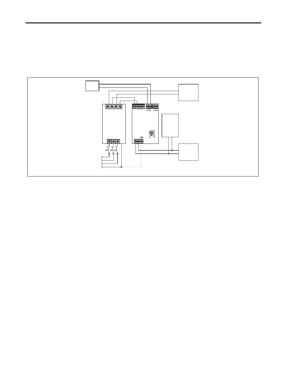
19.7. Example: Decoupling of Branches
Buffer energy supplied from a DC UPS or buffer module is not wasted in “power branches.”
Please note:
Set output voltage of the power supply to a level sufficient to prevent the buffer unit or DC UPS from starting
unexpectedly. Take the voltage drop of the 1606-XLERED into account.
Fig. 19-5
Wiring diagram, decoupling of buffered branches
I
I
I
L1
L2
PE
L3
Buffered
Load
e.g.
Controller
optional
Load
e.g. Motor
Buffer
Module
Failure
Monitor
1606-XLERED
+
-
OUT
+
-
IN 1
+
-
IN 2 IN 1 IN 2
L N PE
10A
Power Supply
+ +
- -
24V, 10A
Note: Whenever possible, use separate mains systems for each power supply.
19.8. Use in a Tightly Sealed Enclosure
When the redundancy module is installed in a tightly sealed enclosure, the temperature inside the enclosure will be
higher than outside. The inside temperature defines the ambient temperature for the redundancy module.
Results from such an installation:
Power supply is placed in the middle of the box; no other heat producer is inside the box.
Enclosure:
Rittal Typ IP66 Box PK 9516 100, plastic, 110x180x165mm
Load:
24V, 16A; (=80%) load is placed outside the box
Input:
24Vdc
Temperature inside enclosure:
58.8°C (in the middle of the right side of the power supply with a distance of 2cm)
Temperature outside enclosure: 24.6°C
Temperature rise:
34.2K