Example: n+1 redundancy up to 30a, Example: battery back-up – Rockwell Automation 1606-XLERED Power Supply Reference Manual User Manual
Page 15
All parameters are specified at 24V, 2.5A, 230Vac input, 25ªC ambient and after a 5 minutes run-in time unless noted otherwise.
Rockwell Automation Publication 1606-RM033A-EN-P — March 2014
15
Bulletin 1606 Switched Mode Power Supplies
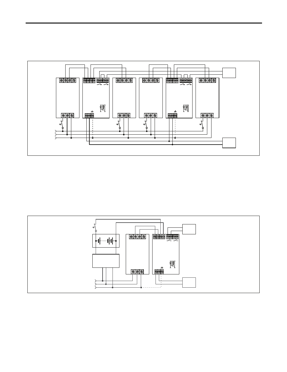
19.4. Example: N+1 Redundancy up to 30A
N+1 Redundancy up to 30A requires four 10A power supplies and two 1606-XLERED redundancy modules.
Fig. 19-2
Wiring diagram, n+1 Redundancy, 30A output current
optional
I
I
L
N
PE
I
L N PE
10A
Power Supply
+ +
- -
24V, 10A
L N PE
10A
Power Supply
+ +
- -
24V, 10A
L N PE
10A
Power Supply
+ +
- -
24V, 10A
Failure
Monitor
30A
Load
1606-XLERED
+
-
OUT
+
-
IN 1
+
-
IN 2 IN 1 IN 2
1606-XLERED
+
-
OUT
+
-
IN 1
+
-
IN 2 IN 1 IN 2
L N PE
10A
Power Supply
+ +
- -
24V, 10A
I
optional
Note: Whenever possible, use separate mains systems for each power supply.
19.5. Example: Battery Back-up
A battery back-up with 10A requires one 10A power supply and one 1606-XLERED redundancy module.
Please note:
Set output voltage of power supply to 26.5Vdc minimum to ensure that the load current is delivered from the power
supply and not from the charger (battery). Use a fuse between the battery and the 1606-XLERED module!
Fig. 19-3
Wiring diagram, 10A Battery back-up
optional
L
N
PE
24V Battery
I
Battery
Charger
+
-
Failure
Monitor
10A
Load
L N PE
10A
Power Supply
+ +
- -
24V, 10A
1606-XLERED
+
-
OUT
+
-
IN 1
+
-
IN 2 IN 1 IN 2