Him display panel descriptions, Him control panel descriptions – Rockwell Automation 1305 FRN. 6.XX Reference Guide User Manual
Page 5
Rockwell Automation Publication 1305-5.2.2 - September 2013
5
1305 Adjustable Frequency AC Drive
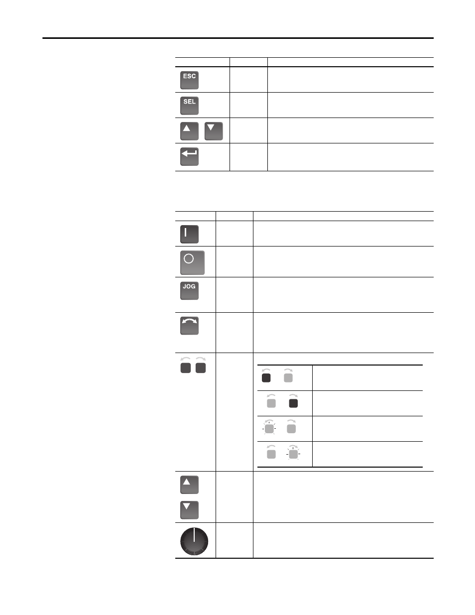
HIM Display Panel
Descriptions
HIM Control Panel
Descriptions
Item
Name
Description
Escape
When pressed, the ESCape key will cause the programming system to go back one
level in the menu structure.
Select
Pressing the SELect key alternately moves the cursor to the next active area. A
flashing first character indicates which line is active.
Increment/
Decrement
These keys are used to increment and decrement a value or scroll through different
groups or parameters.
Enter
When pressed, a group or parameter will be selected or a parameter value will be
entered into memory. After a parameter has been entered into memory, the top line
of the display will automatically become active, allowing another parameter (or
group) to be chosen.
Item
Name
Description
Start
The Start key will initiate drive operation if no other control devices are sending a Stop
command. This key can be disabled by the [Logic Mask] or [Start Mask].
Stop
If the drive is running, pressing the Stop key will cause the drive to stop, using the selected
stop mode. See [Stop Select] in the User Manual.
If the drive has stopped due to a fault, pressing this key will clear the fault and reset the
drive. See [Flt Clear Mode], [Logic Mask], and [Fault Mask].
Jog
When pressed, jog will be initiated at the frequency set by [Jog Frequency], if no other
control devices are sending a Stop command. Releasing the key will cause the drive to stop,
using the selected stop mode. See [Stop Select], [Logic Mask], and [Jog Mask].
Important: If the drive is running prior to issuing a jog command, the jog command will be
ignored. A start command from another source will override the jog command.
Change
Direction
Pressing this key will cause the drive to ramp down to zero Hertz and then ramp up to set
speed in the opposite direction. The appropriate Direction LED will illuminate to indicate the
direction of motor rotation. See [Logic Mask] and [Direction Mask]. Note that the factory
default for control of the reverse function is the reverse input at TB2. To enable the HIM
control of the reverse function, change ‘Bit 0’ of the [Direction Mask] parameter to ‘0’ to
disable the reverse function at TB2.
Direction LEDs
(Indicators)
These LEDs illuminate to indicate the direction of motor rotation.
Increment/
Decrement
Arrows
(only available
with digital
speed control)
Pressing these keys will increase or decrease the HIM frequency command. An indication of
this command will be shown on the visual Speed Indicator LEDs. The drive will run at this
command if the HIM is the selected frequency reference. See [Freq Select 1/2].
Pressing both keys simultaneously stores the current HIM frequency command in HIM
memory. The Speed Indicator LEDs will flash momentarily to indicate a successful save (if
speed is above 20 percent). Cycling power or connecting the HIM to the drive will set the
frequency command to the value stored in HIM memory.
Analog Speed
Potentiometer
If the Analog Speed Potentiometer option has been ordered, the Increment/Decrement keys
and Speed Indicator will be replaced by the pot.
Rotating ‘Forward’
Rotating ‘Reverse’
Changing Direction, Decelerating ‘Reverse’, will begin
to Accelerate ‘Forward’.
Changing Direction, Decelerating ‘Forward’, will begin
to Accelerate ‘Reverse’.
OFF
Steady ON
Steady ON
OFF
Flashing
Steady ON
Steady ON
Flashing