Functional diagram, Front side and user elements, Ab c d – Rockwell Automation 1606-XLSBUFFER24 Power Supply Reference Manual User Manual
Page 6
All parameters are specified at 24V, 20A, 25°C ambient and after a 5 minutes run-in time, unless noted otherwise.
6
Rockwell Automation Publication 1606-RM026A-EN-P — April 2014
Bulletin 1606 Switched Mode Power Supplies
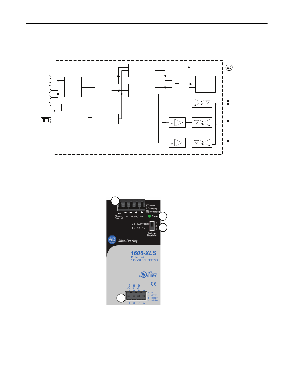
8. Functional Diagram
Fig. 8-1 Functional diagram
Buffer Capacitor
Charger &
Inrush Limiter
Buffer
Capacitor
Buffer Capacitor
Discharger
Status
lamp
7 Active
6 +
Ready Monitor
+
-
Active Monitor
+
-
Optokoppler
Optokoppler
8 Ready
9 Inhibit
Optokoppler
Buffer
Capacitor
Shut-Down
Input / Output
Voltage Monitor
Back-up
Level
Selector
Reverse-
Polarity
Protection
-
-
+
+
Safety and
Over-
Voltage
Protection
Chassis
Ground
9. Front Side and User Elements
Fig. 9-1 Front side
A. I/O Power Port
Quick-connect spring-clamp
terminals,
+
Positive terminal
-
Negative terminal
Chassis Ground
to bond the housing
B. Status lamp
OFF:
Buffer is discharged, or
terminal voltage is below 22V
ON:
Unit is fully charged
Flashes 1,25Hz:
Unit is in charging mode
Flashes 10Hz:
Unit is in discharging mode
C. Signal Port
Plug Connector
6
common + pole
7
Active
: unit is buffering
8
Ready
: unit is on stand-by
9
Inhibit
: initiates buffer
discharging and inhibits
recharging of capacitors
D. Back-up threshold jumper
1-2:
Variable mode
Unit switches to buffer mode when input
voltage decreases by 1V within 0.54V/s or
the input voltage falls below 22.5V.
2-3:
Fixed mode, (factory setting)
Unit switches to buffer mode as soon as the
voltage falls below 22.5V
Missing jumper = 22.5V fixed
Set the unit to fixed mode:
-
when using other power supplies
than the 1606-XLS series
-
with back-feeding loads
-
when the buffer unit is placed close to
the load
-
whenever in doubt
Set the unit to variable mode:
-
for 28V applications
-
when the buffer unit is placed close to
the power supply
A
B
C
D