Rockwell Automation 1494V-DS400_DS600 Disconnect Switch (400/600A - Series A) User Manual
Page 6
1025456
2
DISCONNECT SWITCH AND ACCESSORY KITS
INSTALLATION INSTRUCTION SHEET
1
42052-073
OF
N/A
N/A
N/A
REVISION
AUTHORIZATION
DR.
CHKD.
APPD.
DATE
DATE
DATE
E - DOC
LOCATION: MILWAUKEE, WISCONSIN U.S.A.
B-vertical.ai
DWG.
SIZE
SHEET
B
1
2
3
4
5
6
7
8
A
B
C
D
E
F
G
H
REFERENCE
DIMENSIONS APPLY BEFORE
SURFACE TREATMENT
(DIMENSIONS IN INCHES)
TOLERANCES UNLESS
OTHERWISE SPECIFIED
.XX:
.XXX:
ANGLES:
42052
---------------
---------------
---------------
---------------
---------------
---------------
6
8
1006259
1
2
3
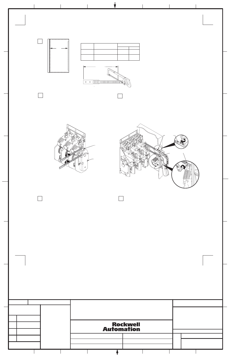
Connecting
Rod
Min.
Max.
"N"
Standard
Extended
Catalog Number
1494V-RB1
1494V-RB2
9"
9-1/4"
9"
23"
Connecting Rod Installation
Right Hand Operation
Connecting Rod Adjustment Procedure
N
Enclosure
Working Depth
(Flange to
Mounting Plate)
N - 3"
Front
Connecting
Link
a) Install connecting rod into the support rod bracket and
thread in clockwise (5) full turns
b) Install connecting rod into the drive bar mechanism
and thread in clockwise (9) full turns
a) Place the disconnect handle in the "OFF" position. Attach
the end of the connecting rod to the primary link of the handle
with two 1/4-20 x 1/2" slotted head screw assemblies and
tighten to 40 lb-in torque.
b) Attach the second connecting rod to the top of the spring
bracket with two 1/4-20 x 1/2" slotted head screw assemblies
and tighten to 40 lb-in torque.
c) Attach the two springs to the mechanism as shown below:
4
5
"ON" Position
a) Move disconnect handle to the "ON" position.
b) If switch does not fully close, return handle to "OFF"
position.
c) Loosen and remove the two 1/4-20 slotted hex head screw
assemblies that hold the connecting rod to the connecting link.
d) Turn connecting rod counter-clockwise (1) full turn.
e) Re-assemble the two 1/4-20 hex head assemblies and
tighten to 40 lb-in and re-test.
f) Repeat 4a - 4e as necessary.
"OFF" Position
g) Move disconnect handle to the "OFF" position.
h) If switch does not fully open, return handle to "ON" position.
j) Loosen and remove the two 1/4-20 slotted hex head screw
assemblies that hold the connecting rod to the connecting link.
k) Turn connecting rod clockwise (1) full turn.
l) Re-assemble the two 1/4-20 hex head assemblies and tighten
to 40 lb-in and re-test.
m) Repeat 5g - 5l as necessary.
(6)
Spring
Bracket
Support Rod
Bracket
Drive Mechanism
THIS DRAWING IS THE PROPERTY OF
ROCKWELL AUTOMATION, INC.
OR ITS SUBSIDIARIES AND MAY NOT BE COPIED,
USED OR DISCLOSED FOR ANY PURPOSE
EXCEPT AS AUTHORIZED IN WRITING BY
ROCKWELL AUTOMATION, INC.