E - doc, Disconnect switch installation 1 – Rockwell Automation 1494V-DS400_DS600 Disconnect Switch (400/600A - Series A) User Manual
Page 3
1025456
2
3
8
DISCONNECT SWITCH AND ACCESSORY KITS
INSTALLATION INSTRUCTION SHEET
1
1006259
42052-073
OF
N/A
N/A
N/A
REVISION
AUTHORIZATION
DR.
CHKD.
APPD.
DATE
DATE
DATE
E - DOC
LOCATION: MILWAUKEE, WISCONSIN U.S.A.
B-vertical.ai
DWG.
SIZE
SHEET
B
1
2
3
4
5
6
7
8
A
B
C
D
E
F
G
H
REFERENCE
DIMENSIONS APPLY BEFORE
SURFACE TREATMENT
(DIMENSIONS IN INCHES)
TOLERANCES UNLESS
OTHERWISE SPECIFIED
.XX:
.XXX:
ANGLES:
42052
---------------
---------------
---------------
---------------
---------------
---------------
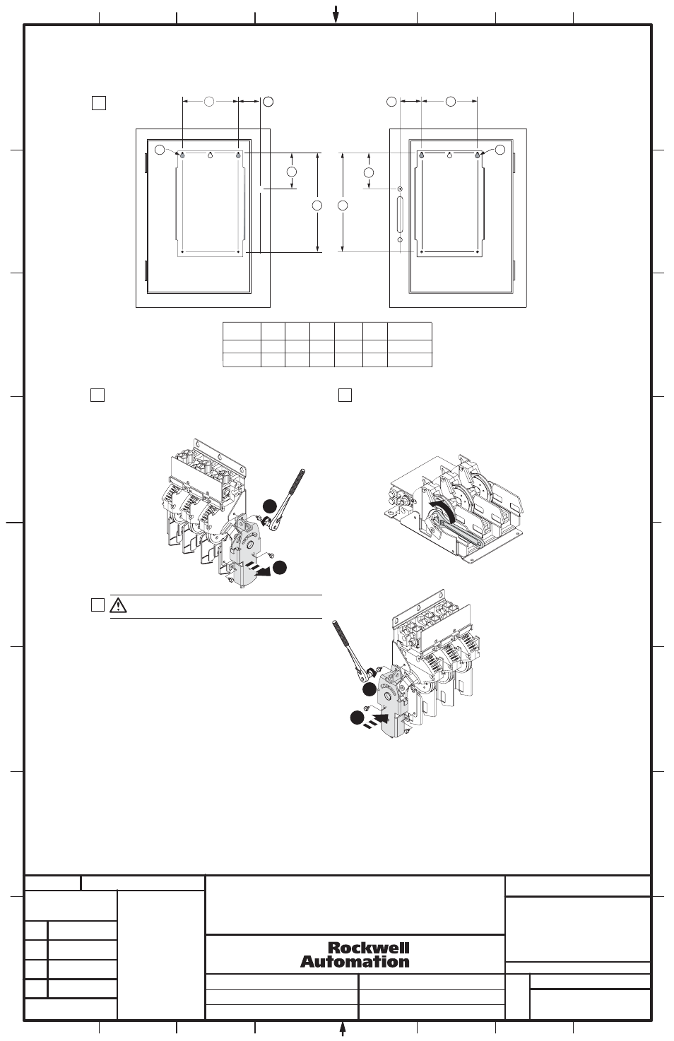
Disconnect Switch Installation
1
2 - 5/64"
6 - 5/32" 8 - 17/64" 14 - 31/32"
(4) 5/16-18
2 - 5/64"
AA
BB
CC
DD
NEMA
SIZE
400A
2 - 5/64"
6 - 5/32" 8 - 17/64" 14 - 31/32"
(4) 5/16-18
2 - 5/64"
600A
GG
HH
BB
BB
DD
CC
AA
AA
AA
AA
AA
AA
Locate
Disconnect
Switch
Right Hand Flange
Left Hand Flange
HH
DD
GG
CC
HH
Rotate the crossbar assembly to the "ON" position (blades fully
engaged - not visible).
(Use any convenient adjustable wrench to aid in rotating the
crossbar & moveable blades.
ATTENTION: Do not attempt to change the position of the
drive mechanism after removal from the disconnect assembly.
With the disconnect switch in the "OFF" position, (blades visible)
loosen and remove the (3) hex head screws.
Remove the drive mechanism from the right-hand side of the
disconnect switch.
Save the (3) 5/16-18 hex head screws shown below.
Conversion from Right-Hand Installation to Left-Hand Installation
2
3
4
40-60 lb-in
(3)
Position the drive mechanism assembly as shown below and install
the (3) 5/16-18 hex head screws.
L1
L2
L3
L1
L2
L3
L1
L2
L3
THIS DRAWING IS THE PROPERTY OF
ROCKWELL AUTOMATION, INC.
OR ITS SUBSIDIARIES AND MAY NOT BE COPIED,
USED OR DISCLOSED FOR ANY PURPOSE
EXCEPT AS AUTHORIZED IN WRITING BY
ROCKWELL AUTOMATION, INC.
2
1
1
2