Display panel description, Control panel description, Faults – Rockwell Automation 1336S ADJ FREQ AC DRIVE User Manual
Page 3
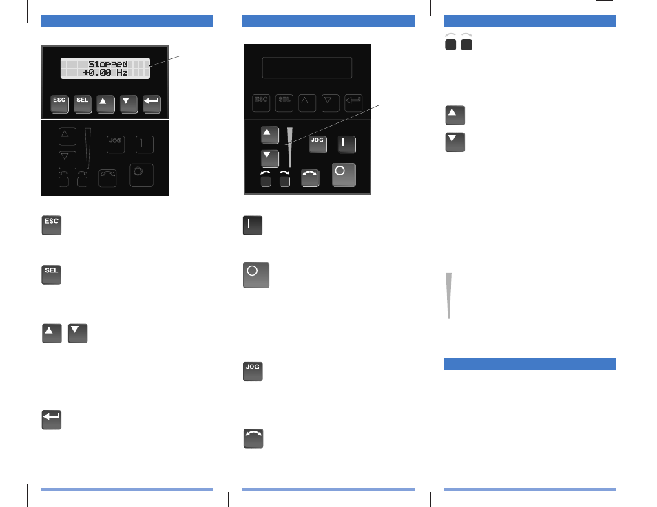
Display Panel Key Descriptions
Control Panel Key Descriptions
Faults
LCD Display
Enter
When pressed, a group or parameter will be
selected or a parameter value will be entered
into memory. After a parameter has been
entered into memory, the top line of the dis-
play will automatically become active,
allowing another parameter (or group) to be
chosen.
Escape
When pressed, the ESCape key will cause
the programming system to go back one
level in the menu tree.
Select
Pressing the SELect key alternately causes
the top or bottom line of the display to
become active. The flashing first character
indicates which line is active.
Increment/Decrement
These keys are used to increment
and decrement a value or scroll
through different groups or parame-
ters. Pressing both keys simultane-
ously while the Process or Password
Display is shown, will save that dis-
play as the startup display.
Digital Speed
Control and
Indicator
(also available
with Analog
Speed Pot.)
Start
The Start key will initiate drive operation if
no other control devices are sending a Stop
command.
Stop
If the drive is running, pressing the Stop key
will cause the drive to stop, using the select-
ed stop mode. Refer to the [Stop Select 1] &
[Stop Select 2] parameters.
If the drive has stopped due to a fault, press-
ing this key will clear the fault and reset the
drive. Refer to the [Flt Clear Mode], [Logic
Mask] and [Fault Mask] parameters.
Jog
When pressed, jog will be initiated at the fre-
quency set by the [Jog Frequency] parameter,
if no other control devices are sending a Stop
command. Releasing the key will cause the
drive to stop, using the selected stop mode.
Change Direction
Pressing this key will cause the drive to ramp
down to zero Hertz and then ramp up to set
speed in the opposite direction. The appropri-
ate Direction Indicator will illuminate to
indicate the direction of motor rotation.
Up/Down Arrows
(only available with digital speed control)
Pressing these keys will increase or decrease
the HIM frequency command. An indication
of this command will be shown on the visual
Speed Indicator. The drive will run at this
command if the HIM is the selected frequen-
cy reference. See [Freq Select 1/2]. Pressing
both keys simultaneously stores the current
HIM frequency command in HIM memory.
Cycling power or removing the HIM from
the drive will set the frequency command to
the value stored in HIM memory. If the
Analog Speed Potentiometer option has been
ordered, the Up/Down keys and Speed
Indicator will be replaced by the pot.
Speed Indicator
(only available with digital speed control)
Illuminates in steps to give an approximate
visual indication of the commanded speed.
If the Analog Speed Potentiometer option
has been ordered, the Up/Down keys and
Speed Indicator will be replaced by the pot.
Direction LEDs (Indicators)
The appropriate LED will illuminate contin-
uously to indicate the commanded direction
of rotation. If the second LED is flashing,
the drive has been commanded to change
direction, but is still decelerating.
Adptr Freq Err
Frequency reference greater than 32767
65
sent to drive.
Auxiliary Fault
Auxiliary input interlock open. Check
02
TB3 connections. If option not installed,
set [Input Mode] to “1.”
BGND 10ms Over
Processor loop fault. Occurs if 10ms
51
background task hasn’t run in 15ms.
Blwn Fuse Flt
Bus fuse in 30 kW (40 HP) & up drives
58
has blown. Locate cause and replace.
Diag C Lim Flt
Drive output current exceeds the hard-
36
ware current limit & [Cur Lim Trip En]
is enabled. Check programming of [Cur
Lim Trip En]. Check for excess load.