Rockwell Automation 1606-XLS240-UPS Power Supply Reference Manual User Manual
Page 9
All parameters are specified at 24V, 10A output load, 25°C ambient and after a 5 minutes run-in time unless noted otherwise.
It is assumed that the input power source can deliver a sufficient output current.
Rockwell Automation Publication 1606-RM036A-EN-P — April 2014
9
Bulletin 1606 Switched Mode Power Supplies
Example: How to determine the expected buffer time for other battery types and battery sizes
Step 1
Check the datasheet of the battery which is planned to be used and look for the discharging curve.
Sometimes, the individual discharging curves are marked with relative C-factors instead of current
values. This can easily be converted. The C-factor needs to be multiplied by the nominal battery
capacity to get the current value. E.g.: 0.6C on a 17Ah battery means 10.2A.
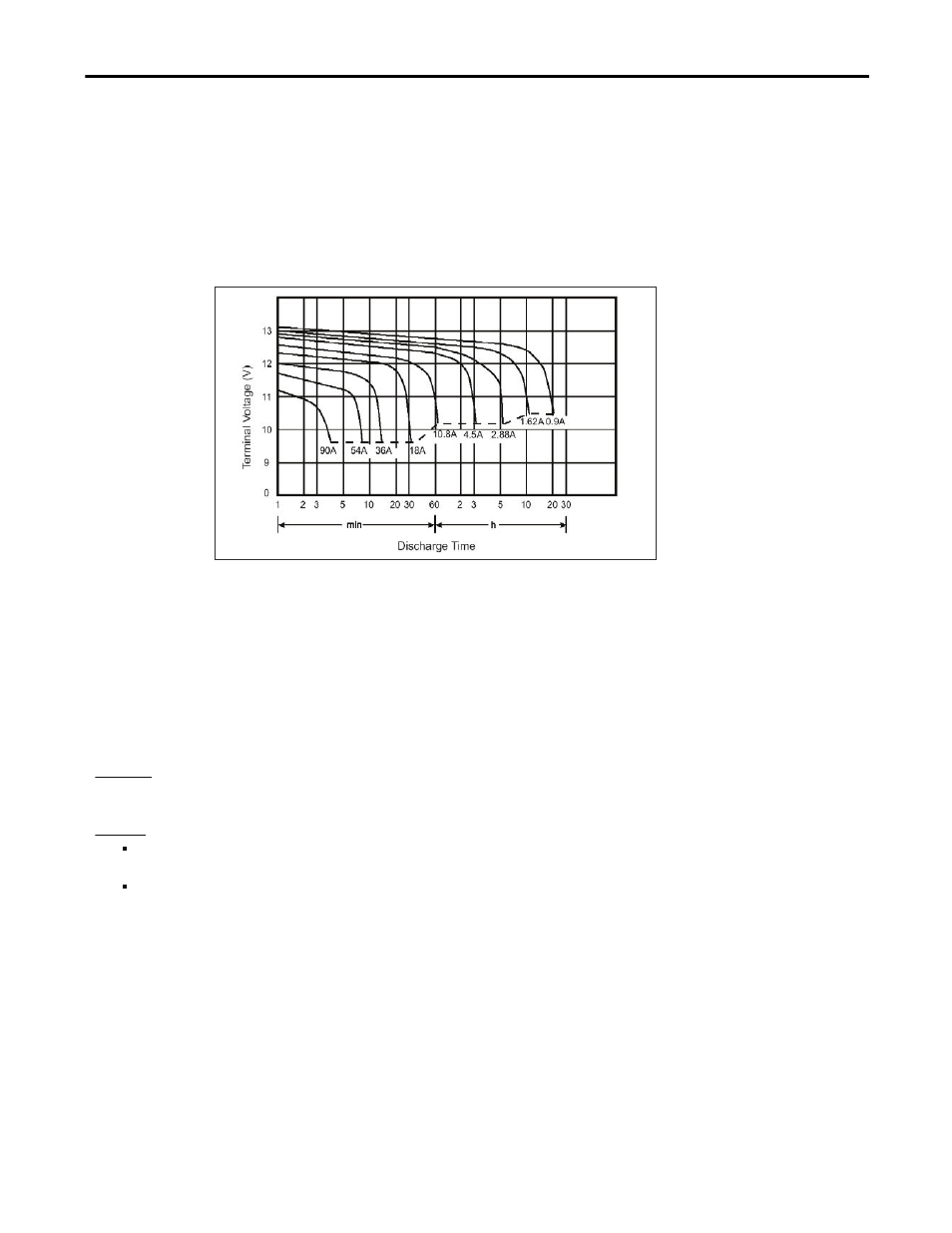
Fig. 9-2 Typical discharging curve of a typical 17Ah battery, curve taken from a
manufacturer’s datasheet
Step 2
Determine the required battery current. Use Fig. 8-1 “Battery discharging current vs. output current” to
get the battery current. Fig. 8-1 requires the average voltage on the battery terminals. Since there is a
voltage drop between the battery terminals and the battery input of the DC-UPS, it is recommended to
use the curve A or B for output currents > 3A or when using long battery cables. In all other situations,
use curve C.
Step 3
Use the determined current from Step 2 to find the appropriate curve in Fig. 9-2. The buffer time
(Discharging Time) can be found where this curve meets the dotted line. This is the point where the DC-
UPS stops buffering due to the under-voltage lockout.
Step 4
Depending on Fig. 9-2, the buffer time needs to be reduced to take aging effects or guaranteed values
into account.
Example:
The buffer current: is 7.5A and a battery according to Fig. 9-2 is used. The cable linking the battery to the DC-UPS is 1m long
and has a cross section of 2.5mm
2
. What is the maximum achievable buffer time?
Answer:
According to Fig. 8-1, the battery current is 18A. Curve A is used, since the battery current is > #A and the
length of the cable is one meter.
According to Fig. 9-2, a buffer time (Discharging Time) of 30 Minutes can be determined. It is recommended
to reduce this figure to approximately 24 minutes for a guaranteed value and to cover the effects of aging.