Relay contacts and inhibit input – Rockwell Automation 1606-XLS240-UPS Power Supply Reference Manual User Manual
Page 12
All parameters are specified at 24V, 10A output load, 25°C ambient and after a 5 minutes run-in time unless noted otherwise.
It is assumed that the input power source can deliver a sufficient output current.
12
Rockwell Automation Publication 1606-RM036A-EN-P — April 2014
Bulletin 1606 Switched Mode Power Supplies
13. Relay Contacts and Inhibit Input
The DC-UPS is equipped with relay contacts and signal inputs for remote monitoring and control of the input.
Relay contacts:
Ready:
Contact is closed when battery is charged more than 85%, no wiring failure is recognized, input
voltage is sufficient and inhibit signal is inactive.
Buffering: Contact is closed when unit is buffering.
Replace Battery:
Contact is closed when the unit is powered from the input and the battery quality test (SoH test)
reports a negative result.
Relay contact ratings
max
60Vdc 0.3A, 30Vdc 1A, 30Vac 0.5A resistive load
min
1mA at 5Vdc min.
Isolation voltage
max
500Vac, signal port to power port
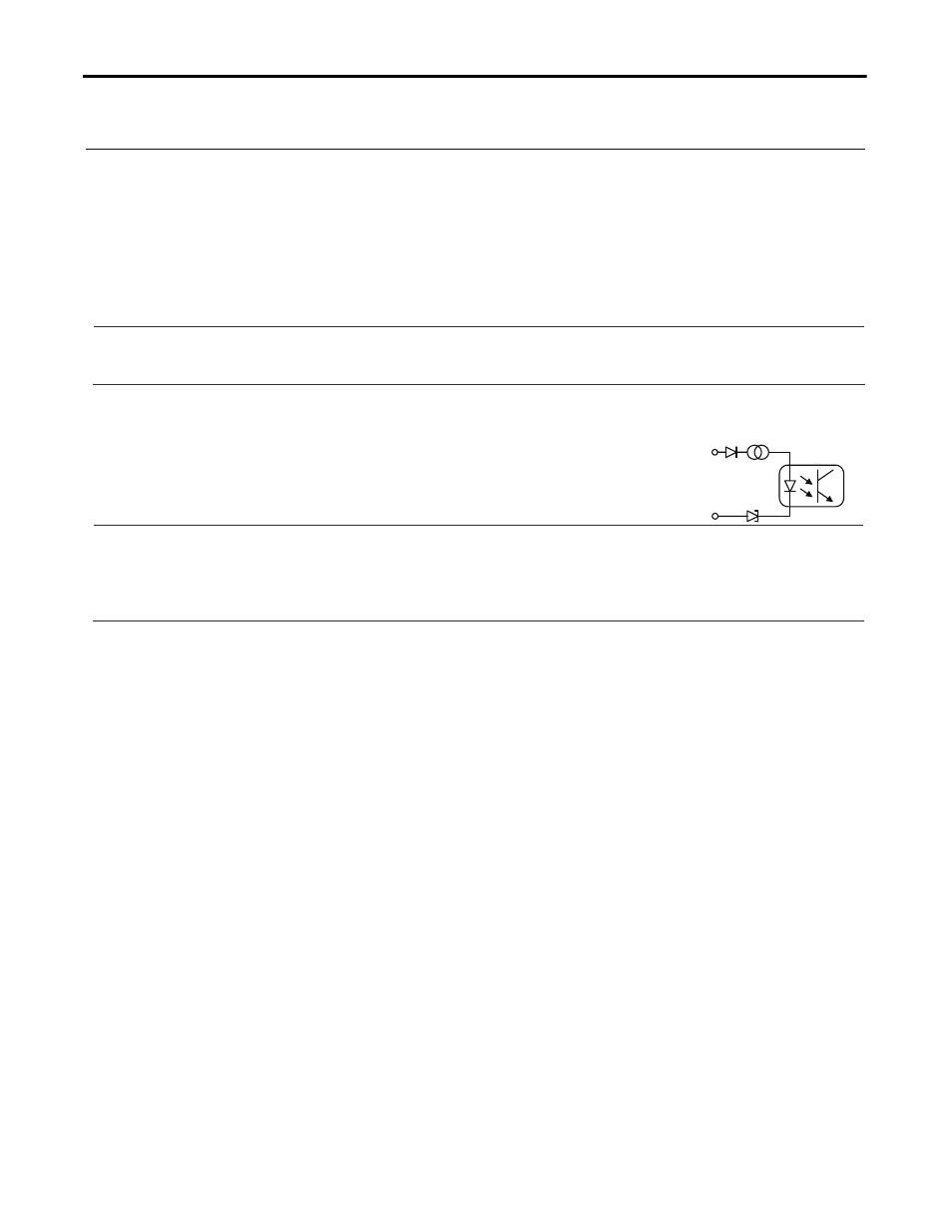
Signal input:
7 +
5,1V
3mA
Inhibit
8 -
Inhibit:
The inhibit input disables buffering. In normal mode, a static signal is
required. In buffer mode, a pulse with a minimum length of 250ms is
required to stop buffering. The inhibit is stored and can be reset by
cycling the input voltage. See also section 26.1 for application hints.
Signal voltage
max. 35Vdc
Signal current
max. 6mA, current limited
Inhibit threshold
min.
6Vdc, buffering is disabled above this threshold level.
max. 10Vdc
Isolation
nom. 500Vac, signal port to power port
Restrictions apply when using the signal and relay contacts in a Haz-Loc environment:
The Buffering, Ready and Replace Battery contact is intended to be used for a separately investigated nonincendive field wiring
and/or field wiring apparatus. The DC-UPS may be located in a Class I, Division 2 (Group A, B, C or D) hazardous (classified)
location. Associated apparatus must be installed in accordance with its manufacturer’s control drawing and Article 504 of the
National Electrical Code (ANSI/NFPA 70) for installation in the United States, or Section 18 of the Canadian Electrical Code for
Installations in Canada.
Selected associated apparatus must be third part listed as providing nonincendive field circuits for the application, and have Voc
not exceeding Vmax, Isc not exceeding Imax.
Non associated nonincendive field wiring apparatuses shall not be connected in parallel unless this is permitted by the associated
nonincendive field wiring apparatuses approval.