V. wiring diagrams (cont’d), Cable “a, Cable “b – Rockwell Automation 1492-CM1771-LD0014F Field Wire Conversion Module User Manual
Page 9
PN-114286
DIR 10000060097 (Version 01)
Publication 1492-IN050B-EN-E
1756-OA16
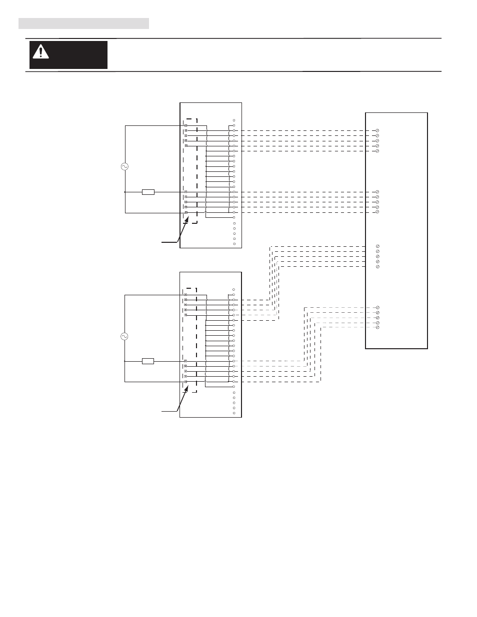
V. Wiring Diagrams (Cont’d)
There are several key application considerations and system specifications (bottom of drawing) when
using these components (conversion module, cable and input module). Read and understand these
considerations before installation.
WARNING
Conversion Module
1492-CM1771-LD014
Conversion Module
1492-CM1771-LD014
Cable
1492-C005005XG
Conversion: 1771-OM (2) to 1756-OA16 (1)
Conversion Module Installation and Application Considerations
This Bul. 1492 cable consists of 2 separate cables (cable “A” and cable “B”) wired to one 1756-OA16 RTB. Each cable can be either 0.5M
or 1.0M (005=0.5M, 010=1.0M). Ensure that cable A and cable B are connected to the correct module in the conversion.
The 1771-OM module output current limits versus 1756-OA16 limits are as follows:
1771-OM
1756-OA16 w/ 1492-CONCAB005XG
a)
Current/Point
2A
0.5
@
60°C
b) Current/Module
6A
4A @ 60°C
c) Surge Current/Point
20A for 100ms
5A for 43ms
The 1771-OM module is rated 220V to 240V AC. The 1756-OA16 module is rated 74V to 265V AC only.
Refer to your 1771-OM and 1756-OA16 Installation Manual wiring schematics and diagrams for more details. Ensure 1756 output module
ratings are not exceeded.
[Reference Doc: 41171-022 (Version 00)]
Cable “A”
(9)
B
3
4
5
6
7
A
0
1
2
Black
White
Red
Green
Orange
Blue
White/Black
Red/Black
Green/Black
Orange/Black
Blue/Black
Black/White
Red/White
Green/White
Blue/White
Black/Red
White/Red
Orange/Red
Blue/Red
Red/Green
L1-0
L1-0
OUT-0
1
OUT-1
2
OUT-2
3
OUT-3
4
OUT-4
10
OUT-5
OUT-6
OUT-7
5
6
7
8
LOAD
-
+
1
19
3
4
5
6
7
8
9
10
11
12
13
15
16
17
18
20
14
2
24
21
22
23
25
L2-0
B
3
4
5
6
7
A
0
1
2
Black
White
Red
Green
Orange
Blue
White/Black
Red/Black
Green/Black
Orange/Black
Blue/Black
Black/White
Red/White
Green/White
Blue/White
Black/Red
White/Red
Orange/Red
Blue/Red
Red/Green
OUT-8
11
OUT-9
12
OUT-10
13
OUT-11
14
OUT-12
20
OUT-13
OUT-14
OUT-15
15
16
17
18
LOAD
1
19
3
4
5
6
7
8
9
10
11
12
13
15
16
17
18
20
14
2
24
21
22
23
25
L2-1
1771-WA Swing Arm
From 1771-OM
1771-WA Swing Arm
From 1771-OM
L1-1
OUTPUT 03
OUTPUT 02
OUTPUT 01
OUTPUT 00
OUTPUT 07
OUTPUT 06
OUTPUT 05
OUTPUT 04
L1-1
INPUT 11
INPUT 10
INPUT 09
INPUT 08
INPUT 15
INPUT 14
INPUT 13
INPUT 12
L1
L2
L1
L2
Cable “B”
L2-1
19
L2-0
9