V. wiring diagrams – Rockwell Automation 1492-CM1771-LD0014F Field Wire Conversion Module User Manual
Page 4
PN-114286
DIR 10000060097 (Version 01)
Publication 1492-IN050B-EN-E
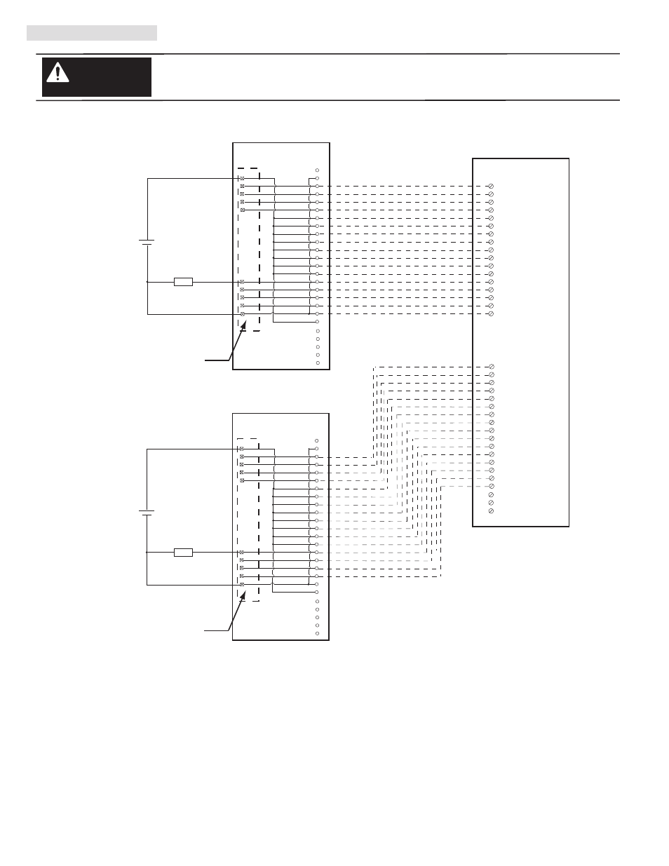
V. Wiring Diagrams
There are several key application considerations and system specifications (bottom of drawing) when
using these components (conversion module, cable and input module). Read and understand these
considerations before installation.
WARNING
1756-IB16I
Conversion: 1771-IQ (2) to 1756-IB16I (1), Sourcing
Conversion Module
1492-CM1771-LD0014
Conversion Module
1492-CM1771-LD0014
Cable
1492-C005005XJ
1771-WA Swing Arm
From 1771-IQ
1771-WA Swing Arm
From 1771-IQ
CABLE”A”
CABLE”B”
Conversion Module Installation and Application Considerations
This Bul. 1492 cable consists of 2 separate cables (cable “A” and cable “B”) wired to one 1756-IB16I RTB. Each cable can be either 0.5M
or 1.0M (005=0.5M, 010=1.0M). Ensure that cable A and cable B are connected to the correct module in the conversion.
The input delay times for the 1771-IQ module versus the 1756-IB16 module are as follows:
1771-IQ
1756-IB16I
w/1492-C005005XJ
a) Off-to-On Delay
12ms (+/-14ms)
1ms max (plus selectable filter)
b) On-to-Off Delay
12ms (+/-14ms)
4ms max (plus selectable filter)
The 1771-IQ module is rated 5V to 30V DC. The 1756-IB16I module is rated 10V to 30V SOURCING DC only.
Refer to your 1771-IQ and 1756-IB16I Installation Manual wiring schematics and diagrams for more details.
For Sinking applications use 1492-CM1771-LD007.
[Reference Doc: 41170-991 (Version 00)]
(4)
B
3
4
5
6
7
A
0
1
2
Black
White
Red
Green
Orange
Blue
White/Black
Red/Black
Green/Black
Orange/Black
Blue/Black
Black/White
Red/White
Green/White
Blue/White
Black/Red
White/Red
Orange/Red
Blue/Red
Red/Green
DC+
GND-0
2
GND-1
4
GND-2
6
GND-3
8
GND-4
1
GND-5
3
GND-6
5
GND-7
7
9
11
13
15
10
12
14
16
GND-15
NOT-USED
LOAD
-
+
1
19
3
4
5
6
7
8
9
10
11
12
13
15
16
17
18
20
14
2
24
21
22
23
25
DC -
GND 00
GND 01
GND 02
GND 03
GND 04
GND 05
GND 06
GND 07
B
3
4
5
6
7
A
0
1
2
Black
White
Red
Green
Orange
Blue
White/Black
Red/Black
Green/Black
Orange/Black
Blue/Black
Black/White
Red/White
Green/White
Blue/White
Black/Red
White/Red
Orange/Red
Blue/Red
Red/Green
DC +
GND-8
18
OUT-9
20
OUT-10
22
OUT-11
24
GND-12
17
GND-13
19
GND-14
21
GND-15
23
25
27
29
31
26
28
30
32
LOAD
-
+
1
19
3
4
5
6
7
8
9
10
11
12
13
15
16
17
18
20
14
2
24
21
22
23
25
DC -
GND 08
GND 09
GND -10
GND -11
GND -12
GND -13
GND -14
GND -15
IN - 0
IN - 1
IN - 2
IN - 3
IN - 4
IN - 5
IN - 6
IN - 7
33
34
35
NOT-USED
-
36
NOT-USED
IN - 8
IN - 9
IN - 10
IN - 11
IN - 12
IN - 13
IN - 14
IN - 15