V. wiring diagrams (cont’d) – Rockwell Automation 1492-CM1771-LD0014F Field Wire Conversion Module User Manual
Page 10
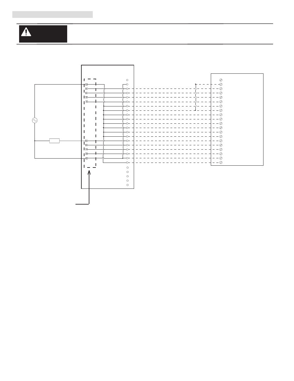
V. Wiring Diagrams (Cont’d)
There are several key application considerations and system specifications (bottom of drawing) when
using these components (conversion module, cable and input module). Read and understand these
considerations before installation.
WARNING
1771-WA Swing Arm
From 1771-ON
Conversion Module
1492-CM1771-LD014
Conversion: 1771-ON to 1756-ON8
1756-ON8
Cable
1492-CONCAB005W
Conversion Module Installation and Application Considerations
This Bul. 1492 cable consists of a cable wired to one 1756-ON8 RTB. Recommended cable lengths of 0.5M or 1.0M (005=0.5M,
010=1.0M). See table 2 for other lengths.
The 1771-ON module output current limits versus 1756-ON8 limits are as follows:
1771-ON
1756-ON8 w/ 1492-CONCAB005W
a)
Current/Point
1.5A
2A
b) Current/Module
6A
5A @ 60°C
c) Surge Current/Point
4A for 10ms
20A for 43ms
The 1771-ON has eight (8) 2A, 250V fuses - 1 per output. The 1756-ON8 is electronically fused per point. Refer to the 1756-ON8
Installation Manual for details on electronic fusing.
Refer to your 1771-ON and 1756-ON8 Installation Manual wiring schematics and diagrams for more details. Ensure 1756 output module
ratings are not exceeded.
[Reference Doc: 41171-021 (Version 00)]
PN-114286
DIR 10000060097 (Version 01)
Publication 1492-IN050B-EN-E
(10)
B
3
4
5
6
7
A
0
1
2
Black
White
Red
Green
Orange
Blue
White/Black
Red/Black
Green/Black
Orange/Black
Blue/Black
Black/White
Red/White
Green/White
Blue/White
Black/Red
White/Red
Orange/Red
Blue/Red
Red/Green
L1
2
NOT USED
OUT-0
1
OUT-1
3
OUT-2
5
OUT-3
7
OUT-4
4
OUT-5
6
OUT-6
8
OUT-7
10
12
14
16
18
11
13
15
17
NOT USED
19
9
L1-0
20
L1-1
LOAD
L2
L1
L1-0
L1-0
L1-0
L1-0
L1-1
L1-1
L1-1
L1-1
1
19
3
4
5
6
7
8
9
10
11
12
13
15
16
17
18
20
14
2
24
21
22
23
25
L2
Output 00
Output 01
Output 02
Output 03
Output 04
Output 05
Output 06
Output 07