Quick installation guide, Cutting connecting rod, Top handle h ole bo tt om handle h ole – Rockwell Automation 1494V-DSxx Series D Variable Depth Disconnect Switch User Manual
Page 2: Top bo tt
A
HOLD FLUSH
TO
INSIDE
OF ENCLOSURE
MEASURE T
O
INSIDE OF
THE
TOP OF ENCLOSURE
TOP HANDLE H
OLE
BO
TT
OM HANDLE H
OLE
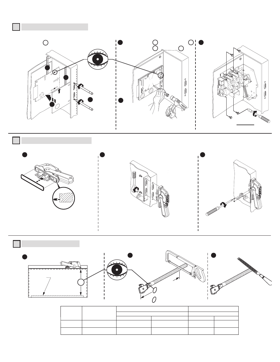
Disconnect Handle Installation
Disconnect Switch Installation (Right hand installation shown. For left hand installation follow similar procedure.)
1
2
Install gasket.
30-40 lb-in
Install handle and spring bracket.
Use template A to locate handle holes on mounting plate.
Overlay template B (30 A - 100 A) over A .
Overlay template C (200 A) over A .
7-11 lb-in
Install defeater lever.
Cutting Connecting Rod
N
Enclosure
Working Depth
(Inside Flange
of Enclosure to
Mounting Plate)
Mounting
Plate
Measure working depth of enclosure.
3
Measure, mark and
cut connecting rod.
N minus 3-1/8"
(30A - 100A)
N minus 3-1/4"
(200A)
23 - 37 lb-in
(30A - 100A)
40 - 60 lb-in
(200A)
TAPE
HOLD FLUSH
TO
INSIDE
OF ENCLOSURE
MEASURE T
O
INSIDE OF
THE
TOP OF ENCL
OSURE
TOP
BO
TT
2
4
A
1
1
5
1
1
2
Remove burrs
3
2
3
Install disconnect switch.
7
6
1
3
A
HOLD FLUSH
TO
INSIDE
OF ENCLOSURE
MEASURE T
O
INSIDE OF
THE
TOP OF E
NCLOSURE
TOP
BO
TT
B
or
C
2 - 1/4"
5 - 1/4"
2 - 1/4"
4 - 11/16"
3 - 1/16"
Switc
h Mounting Holes
Center punc
h and drill (4) 11/64" holes f
or
tap-tite scre
ws pr
ovided with
switc
h
Center punch and
drill (4) holes
for thread forming
(TAP-TITE) screws
provided with switch.
11/64" Dia. (30A - 100A)
7/32" Dia (200A)
PN-47400
DIR 10000056505 (Version 00)
QUICK INSTALLATION GUIDE
(2)
6 - 3/4"
30A - 60A - 100A Disconnect Switches
“N”
Min.
6 - 3/4"
9 - 1/8"
Max.
21 - 5/8"
8 - 1/2"
200A Disconnect Switches
“N”
Min.
8 - 1/2"
10 - 1/4"
Max.
22 - 3/4"
1494V-RA3
1494V-RA4
Catalog
Number
Connecting
Rod
Standard
Extended