Rockwell Automation 442L SafeShield Safety Light Curtain Hardware User Manual
Page 29
SafeShield Safety Light Curtain Hardware User Manual
29
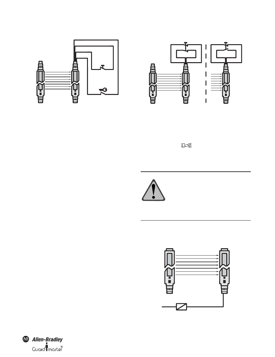
Teach-In Key-Operated Switch
Figure 32: Connection of an external teach-in key-operated switch
Notes
• For teach-in a reset button must be connected to the
SafeShield safety light curtain (see “Reset Button” on
page 28).
• If you connect a teach-in switch to the SafeShield safety
light curtain, then you can no longer use the emergency
stop function in the SafeShield safety light curtain.
• If you use a SafeShield function module then you can also
connect the teach-in key-operated switch to the
switching amplifier.
➢ Ensure that only authorized persons have access to the
teach-in key.
Device symbol SafeShield safety light curtain Host
(receiver), context menu Configuration draft, Edit,
file card General, option Teach-in key-operated switch
active.
Emergency Stop
The emergency stop input has two channels. The emergency stop
monitoring in the device corresponds to stop category 0 in
accordance with EN 418. Switch off at the emergency stop input
(see “Emergency Stop” on page 29) has the same effect as reaching
into the protective field. You can connect the emergency stop input
e.g. to a door switch.
Pin 6
Pin 4
Pin 3
Pin 7
Teach-in key-operated
switch
Switch for
deactivating
the blanking
!
Figure 33: Possible methods of connection of a door switch or similar to
the emergency stop input
You can design the two-channel button as equivalent (N/C, N/C) or
complementary (N/O, N/C). You must configure the SafeShield
safety light curtain as appropriate with the aid of the SCD. If the
configuration and the electrical connection do not match, the
system locks completely (lock-out). The 7-segment display will then
show the error message
.
Device symbol SafeShield safety light curtain Host
(receiver), context menu Configuration draft, Edit,
file card General, option Emergency stop active.
Signal Output (ADO)
Pin 7 on the system connector is a signal output (ADO). You can
use this output for a relay or a PLC.
Figure 34: Connection to the signal output
Equivalent
Complementary
Switching
Pin 7
Pin 3
Pin 4
Pin 6
Pin 7
Pin 3
Pin 4
Pin 6
!
ATTENTION: Device configuration
after replacement!
If you replace a safety light curtain with the
emergency stop function active, then you
must transfer the configuration to the device
again. It is not sufficient to make the
electrical connections, because new devices
are supplied ex factory with deactivated
Emergency stop function.
Pin 7
0V DC