Rockwell Automation 442L SafeShield Safety Light Curtain Hardware User Manual
Page 23
SafeShield Safety Light Curtain Hardware User Manual
23
➢ First, calculate S using the following formula:
S = 2000 × T + 8 × (d – 14) [mm]
Where …
T = Stopping/run-down time of the machine
+ response time of the protective device after light path
interruption [s]
d = Resolution of the light curtain [mm]
S = Safety distance [mm]
The reach/approach speed is already included in the formula.
➢ If the result S is ≤ 500mm, then use the determined value as the
safety distance.
➢ If the result S is > 500mm, then recalculate S as follows:
S = 1600 × T + 8 × (d – 14) [mm]
➢ If the new value S is > 500mm, then use the newly determined
value as the minimum safety distance.
➢ If the new value S is ≤ 500mm, then use 500mm as the safety
distance.
Example:
Stopping/run-down time of the machine = 290 ms
Response time after light path interruption = 30 ms
Resolution of the light curtain = 14mm
T = 290 ms + 30 ms = 320 ms = 0.32 s
S = 2000 Ч 0.32 + 8 Ч (14 – 14) = 640mm
S > 500mm, therefore:
S = 1600 Ч 0.32 + 8 Ч (14 – 14) = 512mm
How to calculate the safety distance D
s
according to ANSI
B11.19-1990 E.4.2.3.3.5 and Code of Federal Regulations,
Volume 29, Part 1910.217 … (h) (9) (v):
Notes The following calculation shows an example calculation of
the safety distance. Depending on the application and the
ambient conditions, a different calculation may be
necessary.
➢ Calculate D
s
using the following formula:
D
s
= H
s
× (T
s
+ T
c
+ T
r
+ T
bm
) + D
pf
Where …
D
s
= The minimum distance in inches (or millimetres) from the
hazardous point to the detection point, plan or zone
H
s
= A parameter in inches/second or millimetres/second,
derived from data on approach speeds of the body or parts
of the body. Often 63 inches/second (1600 millimetres/
second) is used for H
s
.
T
s
= Stopping time of the machine tool measured at the final
control element
T
c
= Response time of the control system
T
r
= Response time of the presence-sensing device and its
interface
T
bm
=Additional response time allowed for brake monitor to
compensate for wear
Notes Any additional time delays must be accounted for in this
calculation.
D
pf
=An additional distance added to the overall safety distance
required. This value is based on intrusion toward the
hazardous point prior to actuation of the electro-sensitive
protective equipment (ESPE). Values range from 0.25 inches
to 48 inches (6 to 1220 millimetres) or more depending on
application.
Example In opto-electronic protection, such as with a
perpendicular safety light curtain applications with
object sensitivity (effective resolution) less than 2.5
inches (64 millimeters), the D
pf
can be approximated
based on the following formula:
D
pf
(inches) = 3.4 × (object sensitivity – 0.276), but not
less than 0.
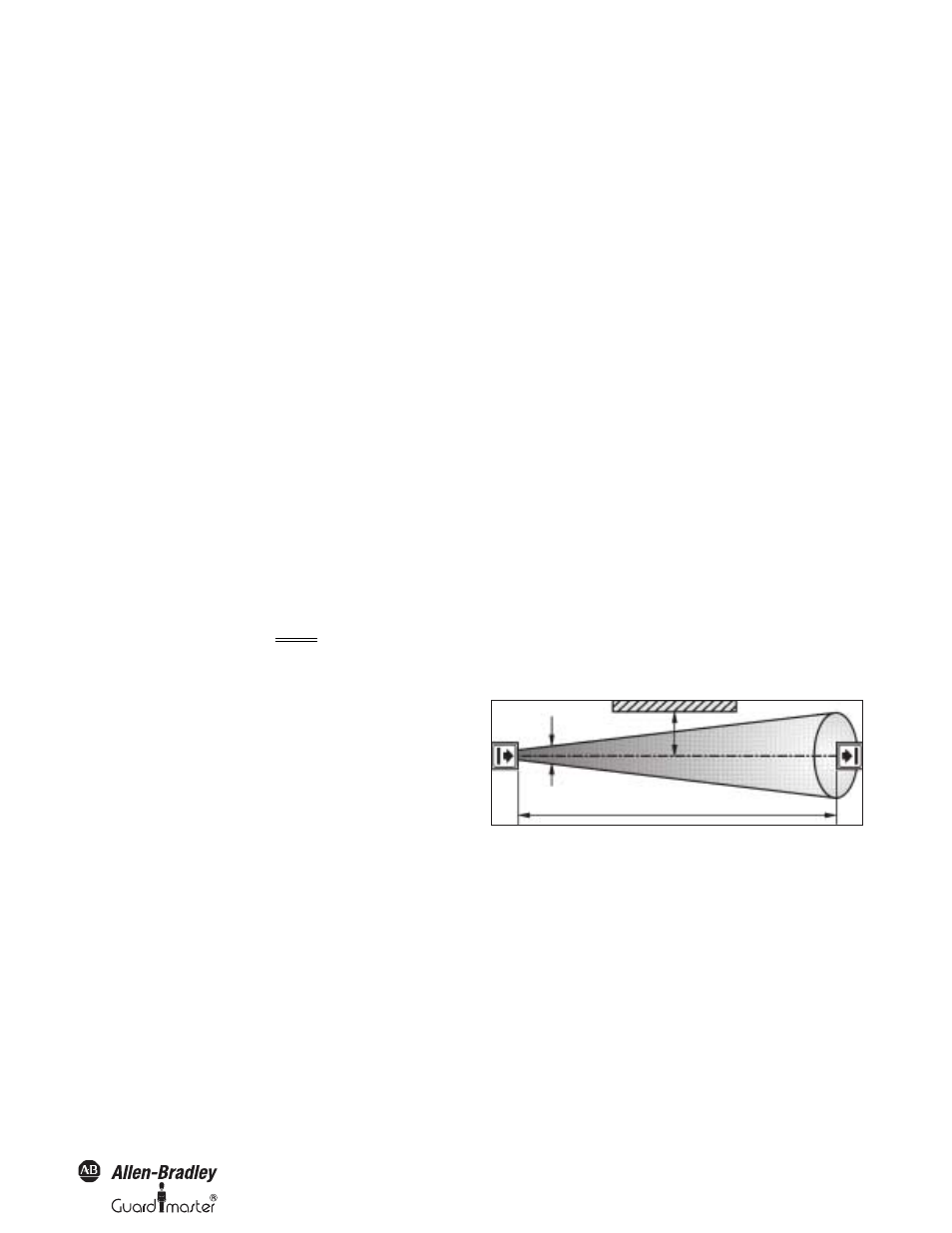
Minimum Distance to Reflective Surfaces
The light beams from the sender may be deflected by reflective
surfaces. This can result in failure to identify an object.
All reflective surfaces and objects (e.g. material bins) must
therefore be located at a minimum distance a from the protective
field of the system. The minimum distance (a) depends on the
distance (D) between sender and receiver.
Figure 20: Minimum distance from reflective surfaces
Notes The field of view of the sender and receiver optics is
identical.
How to determine the minimum distance from reflective
surfaces:
➢ Determine the distance (D) [m] sender-receiver.
➢ Read the minimum distance (a) [mm] from the graph:
Reflective surface
Minimum distance (a)
Field of view
Distance (D) sender-receiver