Rockwell Automation 150 USE MN/SMC DIALOG + CONTROLLER User Manual
Page 67
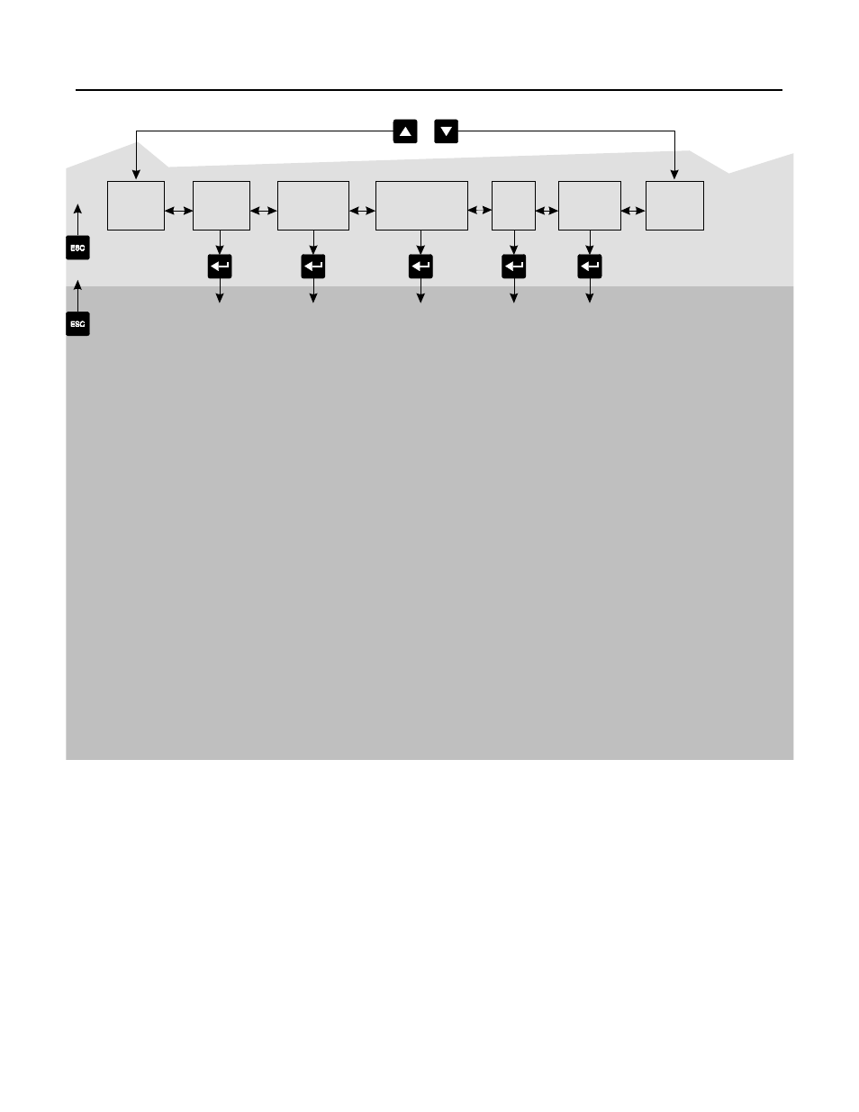
Programming
4-3
Figure 4.1 (Cont.) Menu Structure Hierarchy
①
Steps back one level.
②
English is currently the only available language.
③
For further information on parameters, see Appendix B.
④
For further information on parameter management, see pages 4-6 and 4-7.
Linear
List
Basic Setup
Advanced Setup
Faults
Language
Metering
See
Chapter 6
Calibrate
See
Chapter 5
or
GROUP LEVEL
➁
➀
➀
Volts Phase A–B
Volts Phase B–C
Volts Phase C–A
Current Phase A
Current Phase B
Current Phase C
Wattmeter
Kilowatt Hours
Elapsed Time
Power Factor
Mtr. Therm. Usage
SMC Option
Starting Mode
Ramp Time #1
Initial Torque #1
Curr. Limit Level
Kickstart Time
Stall Delay
Energy Saver
Aux Contacts 1&2
Aux Contact #3
Contact 3 Config
(Option Setting)
Parameter Mgmt
Clear Fault
Fault Buffer #1
Fault Buffer #2
Fault Buffer #3
Fault Buffer #4
Fault Buffer #5
Overload Class
Overload Reset
Motor HP Rating
Motor kW Rating
Line Voltage
Motor FLC
Service Factor
Motor Code Letter
LRC Ration
Converter Rating
CT Ratio
Calibration
Enter Calib. Amps
Current Phase A
Parameter Mgmt.
SMC Option
Starting Mode
Dual Ramp
Ramp Time #1
Initial Torque #1
Ramp Time #2
Initial Torque #2
Curr. Limit Level
Kickstart Time
Stall Delay
Energy Saver
Aux Contacts 1&2
Aux Contact #3
Contact 3 Config
(Option Setting)
Undervolt Level
Undervolt Delay
Overvolt Level
Overvolt Delay
Jam Level
Jam Delay
Unbalance Level
Unbalance Delay
Rebalance
Underload Level
Underload Delay
Phase Reversal
Starts per Hour
Restart Attempts
Restart Delay
ETM Reset
Parameter Mgmt
④
PARAMETER LEVEL
③
④
④