Original instructions, Cables/connectors, M12 connector dimensions [mm (in.) – Rockwell Automation 445L GuardShield Safe 2 and Safe 2 PAC Safety Light Curtains User Manual User Manual
Page 14: Test input to transmitter
R
GuardShield™ Safe 2 Safety Light Curtain User Manual
12
Original instructions
Cables/Connectors
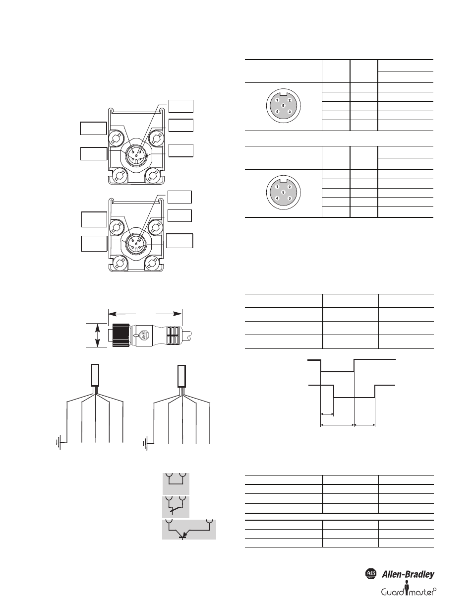
The GuardShield Safe 2 transmitter and receiver connectors are 5-pin
M12 quick-disconnect connectors. Shielded and nonshielded cordsets
are offered in lengths from 2 to 30 meters.
Figure 13: Pin assignment of the M12 connectors
M12 Connector Dimensions [mm (in.)]
Figure 14: Five-pin female connection for Safe 2
GuardShield Safe 2 Receiver Connector pin assignments and wire colors
GuardShield Safe 2 Transmitter Connector pin assignments and wire colors
Test input to transmitter
Normally the test input at the transmitter is installed with a short circuit
jumper to activate the transmitter. If an external test is desired, a contact
can be connected to the test input).
The timing of test input is as follows (Figure 14):
Figure 15: Test timing diagram
t
R
means the response time of the respective Safe 2 type (see product
label).
Transmitter:
Receiver:
Pin 4
= Test 1
Pin 1
= +24V DC
Pin 5
= PE
Pin 3
= 0V
Pin 2
= Test 2
Pin 4
= OSSD 1
Pin 1
= +24V DC
Pin 5
= PE
Pin 3
= 0V
Pin 2
= OSSD 2
47 (1.85)
14
(0.56)
+2
4
V
DC
0 V
OSSD 1
OSSD 2
+
24V
DC
0 V
1)Operation with internal test
2)Test using a relay contract
3)Test using PNP output
Transmitter
3)
2)
PE
Receiver
PE
1 (br
o
w
n
)
3 (bl
u
e)
4 bl
ack)
2 (w
hite)
5 (g
rey)
1)
Te
st
1
Te
st
2
1 (br
o
w
n
)
3 (bl
u
e)
4 bl
ack)
2 (w
hite)
5 (g
rey)
Female Top View
Color
Pin No.
Signal
Receiver
Brown
1
+24V
White
2
OSSD 2
Blue
3
0V
Black
4
OSSD 1
Grey
5
Ground (PE)
Female Top View
Color
Pin No.
Signal
Receiver
Brown
1
+24V
White
2
Test 2
Blue
3
0V
Black
4
Test 1
Grey
5
Ground (PE)
Time
Value in ms
Response time on test signal
t
1
≤ t
R
+ 15
Time to test
t
2
> t
1
Restart time after test
t
3
≤ 800
Internal test
Description
Value
Continuous test current
I
10 mA
Peak test current
I
P
100 mA
Time of peak test current
t
P
20 μs
Internal test
Transmitter
Test LED Transmitter
Short circuited (closed)
Active
Green
Open
Inactive
Red
Short circuit
Test input
OSSD 1/OSSD 2
t3
t2
t1
open