Install the atex option module assembly – Rockwell Automation 20-750-ATEX PowerFlex 750-Series ATEX Option Module User Manual
Page 23
Rockwell Automation Publication 750-UM003B-EN-P - July 2013
23
Installation and Wiring
Chapter 2
Install the ATEX Option
Module Assembly
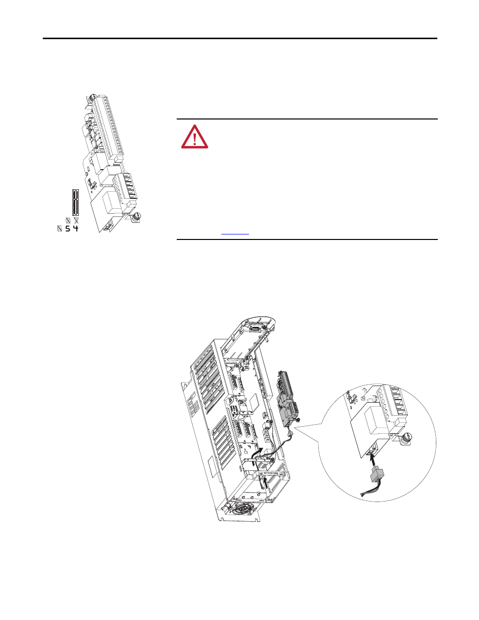
Follow these steps to install the ATEX option module with 11-Series I/O option
module assembly in the drive.
1. Remove power from the drive and verify that the voltage on the bus
capacitors has discharged.
2. Route the thermal sensor wires attached to the ATEX removable terminal
block under the lower mounting bracket.
3. Plug in the removable terminal block and secure the screws before
installing the assembly on the backplane.
ATTENTION: To avoid an electric shock hazard, verify that the voltage on the
bus capacitors has discharged completely before performing any service.
Frames 1…7: Measure the DC bus voltage at the power terminal block by
measuring between the +DC and -DC terminals or between the +DC and -DC test
points if equipped. Also measure between the +DC terminal or test point and the
chassis and between the -DC terminal or test point and the chassis. The voltage
must be zero for all three measurements.
Frames 8…10: Measure the DC bus voltage at the DC+ and DC- test point sockets
on the front of the power module.
See the PowerFlex 750-Series AC Drives Installation Instructions, publication
, for the location of the terminal block and test point sockets.
TIP
Leave enough length in the cable so that you can remove the option module in
the future, if needed.