Circuit status, Operating principle, Fault detection – Rockwell Automation 21G PowerFlex 750 Series Safe Torque Off User Manual
Page 31: Figure 4 - stop category 1 – controlled
Rockwell Automation Publication 750-UM002F-EN-P - July 2013
31
Description of Operation
Chapter 4
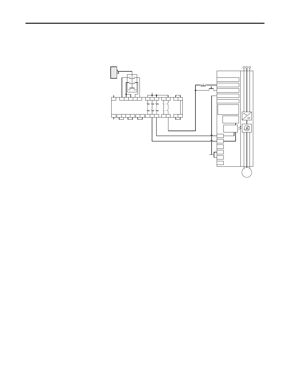
Example 3 - All Drives Safe Torque Off Connection with Controlled
Stop Action, Dual Channel
Figure 4 - Stop Category 1 – Controlled
Circuit Status
Circuit shown with guard door closed and system ready for normal operation.
Operating Principle
This is a dual channel system with monitoring of the Safe Torque Off circuit and
drive. Opening the guard door will switch the input circuits (S11-S12 & S21-
S22) to the Minotaur monitoring safety relay unit. The output circuits (23-24)
will issue a Stop command to the drive and cause a controlled deceleration. After
the programmed delay, the timed output circuits (47-48 & 57-58) will cause the
Safe Torque Off option and the drive Enable circuit to trip. If the motor is
rotating when the trip occurs, it will coast to stop. To restart the drive, the
Minotaur safety relay must first be reset followed by a valid start command to the
drive.
Fault Detection
A single fault detected on the Minotaur safety input circuits will result in the
lock-out of the system at the next operation and will not cause loss of the safety
function.
If the Safe Torque Off option sticks ON, the motor will stop on command due to
the enable input. The system cannot be reset when this fault condition exists.
GuardMaster
Trojan
A1
S21 S11 S52 S12
A2 X1 X2
13 23
14 24
S33
Y2
S34
Y1
X3
37 47 57
38 48 58
X4
S22
Y39 Y40
Minotaur
MSR138DP
SP+
SE+
Sd
SP–
SE–
Sd
Gate
+24V DC
24V DC
Common
External
+24V DC
AC Line
Input Power
Motor
Gate Control
Circuit
Gate Control
Power Supply
Jumpers:
ENABLE Installed
SAFETY Removed
24V DC Common
Start/Stop Common
Start
Stop
+24V DC
PowerFlex
750-Series
Stop
Start
External
+24V DC
Common
External
+24V DC