Pfd and pfh data, Pfd and pfh for 20-year proof test interval, Safe state – Rockwell Automation 21G PowerFlex 750 Series Safe Torque Off User Manual
Page 12: Safety reaction time, Pfd and pfh data safe state safety reaction time
12
Rockwell Automation Publication 750-UM002F-EN-P - July 2013
Chapter 2
Safety Concept
PFD and PFH Data
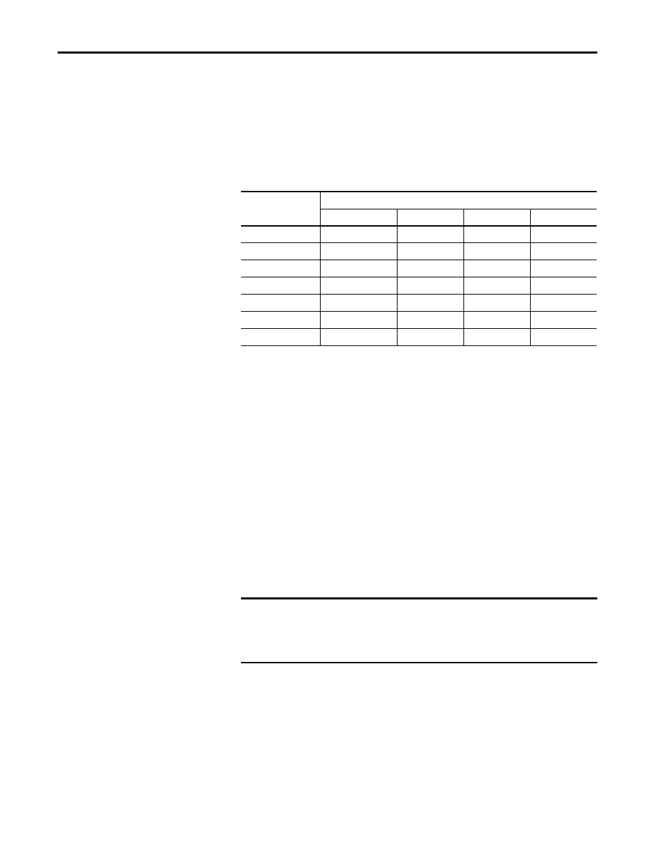
PFD and PFH calculations are based on the equations from Part 6 of IEC 61508.
This table provides data for a 20-year proof test interval and demonstrates the
worst-case effect of various configuration changes on the data.
PFD and PFH for 20-year Proof Test Interval
Safe State
The Safe State encompasses all operation that occurs outside of the other
monitoring and stopping behavior defined as part of the Safe Torque Off Option
module.
If a Safe State Fault is detected, the safety option goes to the Safe State. This
includes faults related to integrity of hardware or firmware.
Safety Reaction Time
The safety reaction time is the amount of time from a safety-related event as
input to the system until the system is in the Safe State.
The safety reaction time from an input signal condition that triggers a safe stop,
to the initiation of the configured Stop Type, is 10 ms (maximum) for drive
Frames 1…10.
Attribute
Value
Drive Frames 1…7
Drive Frame 8
Drive Frame 9
Drive Frame 10
PFD
3.29E-5
1.73E-04
2.65E-4
3.56E-4
PFH
3.75E-10 1/hour
1.99E-9 1/hour
3.04E-9 1/hour
4.09E-9 1/hour
SIL CL
3
3
3
3
PL
e
e
e
e
Category
3
3
3
3
HFT
1 (1oo2)
1 (1oo2)
1 (1oo2)
1 (1oo2)
PTI (Proof Test Interval)
20 years
20 years
20 years
20 years
IMPORTANT
An input signal condition that is present for less than the reaction time may not
result in the safety function being performed. Repeated request of the safety
function for less than the reaction time may result in a spurious detection of a
fault.