Fastener torque specifications, Instructions – Rockwell Automation 1336S_F_T_E_R C-Frame Front End Conversion Kit User Manual
Page 3
1336 PLUS, PLUSII, IMPACT, and FORCE C-Frame Front End Conversion Kit
3
Fastener Torque
Specifications
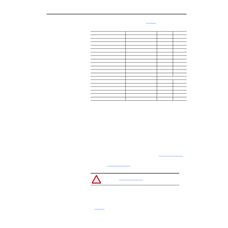
Fastener Torque Specifications are listed in
Table A Fastener Torque Specifications
Instructions
1. Back-up the programming of the drive being converted before
proceeding:
– Store the programming of the drive in the HIM (if applicable to your
HIM) or
– Use Drive Tools, Drive Explorer, or Drive Explorer Light to back-up
the programming of the drive.
2. Remove and lock out the line power from the existing C-frame drive that
will be converted.
3. For disassembly instructions, refer to Chapter 3 in the Troubleshooting
Guide. The 1336-CONVCF-SPxA Kit is shown in
4. An illustration of the CONVCF Kit with numbered cables and wires is
shown in
. The cables have the destination connector
number on them.
5. For assembly instructions refer to Chapter 3 in the Troubleshooting
Guide.
6. Re-connect the power and control wiring. Torque specs are listed in
.
Component
Fastener Application
Torque lb-in.
Torque N-m
Main Control Board Mounting Plate
8 – 10
0.9 – 1.1
Gate Driver Board Mounting Plate
8 – 10
0.9 – 1.1
Precharge Board Mounting Plate
8 – 10
0.9 – 1.1
Bus Capacitor Bank
Bank to chassis
25 – 31
2.8 – 3.5
DC Bus Inductor
Wires to bus bars
25 – 31
2.8 – 3.5
DC Bus Inductor
TB1 mounting plate to chassis
25 – 31
2.8 – 3.5
Snubber Board
Bus bars to capacitor bank
25 – 31
2.8 – 3.5
Snubber Board
Board to SCR1
25 – 31
2.8 – 3.5
Snubber Board
Board to PM1 – PM3
30 – 39
3.4 – 4.4
Power Modules PM1 – PM3
Module to heat sink
25 – 31
2.8 – 3.5
Input Rectifier
Rectifier to heat sink
25 – 31
2.8 – 3.5
Bus Fuse F1
Fuse to chassis
200 – 220
22.6 – 24.8
Thermistor
Thermistor to heat sink
Hand tighten only
TB1
Wires to terminals
25 – 31
2.8 – 3.5
TB2
Wires to terminals
8
0.9
TB3
Wires to terminals
8
0.9
Ground Sense CT
Bracket to chassis
25 – 31
2.8 – 3.5
Ground Sense CT
Positive bus bar junction
25 – 31
2.8 – 3.5
Ground Sense CT
Bus bars to capacitor bank
25 – 31
2.8 – 3.5
!
ATTENTION: Make sure the two shorting devices
shown in
are removed before
connecting into J7 and J8 of the Gate Driver Board.