Description – Rockwell Automation 42DR Intrinsically Safe Sensor User Manual
Page 8
8
#897H--S120 and #897H--S140 Intrinsic Safety Zener
Diode Barrier Information Specifications
Environmental Conditions
Operating Temperatures
--40 to 122F (--40C to +50C)
Storage Temperature
--40F to 167F (--40C to +75C)
Relative Humidity
5% to 95% noncondensation
Vibration Resistance
Vibration Frequency
55Hz
Vibration Amplitude
+1.5mm (+0.062in)
Shock Resistance
20g
Operational Data, Safety Barrier #897H- S120
Input Voltage—Rated
—Max
+24V
+26V
Internal Resistance—Typical
—Tolerance
302
+16
Replaceable Fuse
#23- 155 Rating
80mA
Leakage Current
Micro A
Short Circuit Protection
Yes
Class
I, II, III
Division
1, 2
Groups
A to G
Operational Data, Safety Barrier #897H- S140
Input Voltage—Rated
—Max
+24V
+26V
Voltage Drop Resulting from
Internal Impedance—Typical
—Tolerance
1V
1V @ < 22mA
2V @ > 22mA
Replaceable Fuse
#23- 156 Rating
100mA
Leakage Current
10A
Short Circuit Protection
Yes
Class
I, II, III
Division
1, 2
Groups
A to G
Mounting Accessories
#63- 112
Plastic Mounting Adaptor for Barriers #897H- S120 and #897H- S140
to fit #64- 134 or other EN50022/DIN46277 Mounting Rail.
#64- 134
1m (3.3ft) prepunched zinc plated and chromated steel Mounting Rail
per EN50022/DIN46277 (TS35)
Description
Intrinsic Safety Zener Diode Barriers #897H--S120 and #897H--S140) are
passive protective interface assemblies to isolate intrinsically safe circuits from
non-intrinsically safe circuits as defined in FM Class No. 3610.
Intrinsically safe connections are suitable for hazardous locations classified as:
Class I, II, III
Division 1 or 2
Groups A, B, C, D, E, F, G.
The Intrinsic Safety Zener Diode Barrier offer economical solutions for
instrumentation and control systems in hazardous locations defined by NEC
Article 500.
Principle of the Replaceable Keyed Fuse Assemblies
For the Intrinsic Safety Zener Diode Barriers #897H--S120 & #897H--S140, the
principle of a keyed fuse assembly has been employed. In case of a fault due to
overvoltage, polarity misconnection or transients, only the protective keyed fuse
assembly needs to be replaced. Disassembly, disconnection of the wiring, or
even disposing of the entire barrier is eliminated, thus providing a very
economical solution for application of Intrinsic Safety Zener Diode Barriers.
The protective fuse is securely embedded in a keyed fuse assembly. This keyed
assembly is coded for a defined fuse rating. Only the properly rated keyed fuse
assembly is able to be inserted in the appropriate barrier.
The replacement of the fuse assembly can be done by the user at the job site.
The barriers do not have to be returned to the manufacturer for replacement.
See Operational Data for #897H--S120 and #897H--S140 in Specifications for
proper Replaceable Fuse selection.
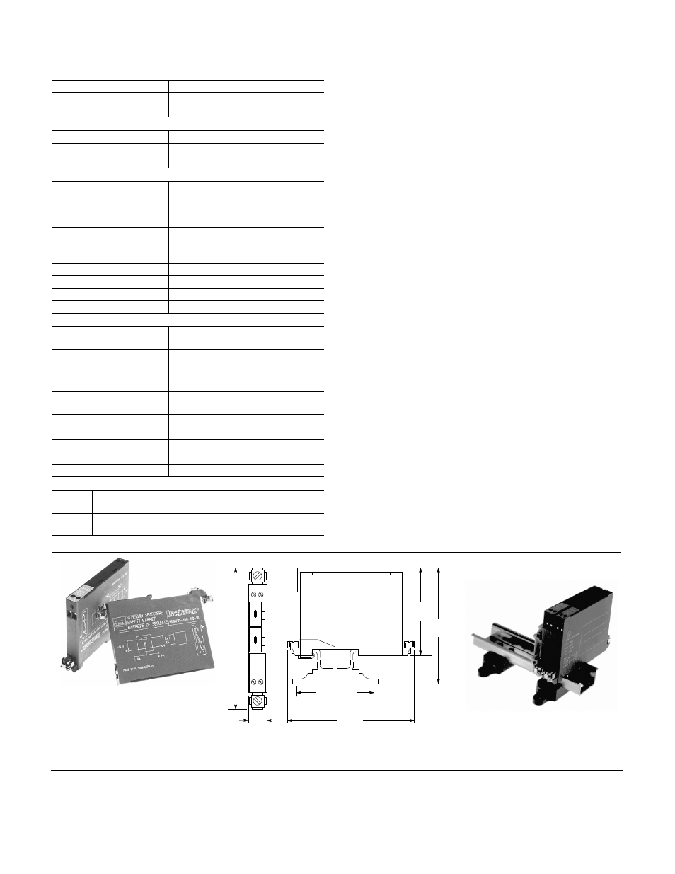
4
(102)
#897H--S120 or #897H--S140
Intrinsic Safety
Zener Diode Barrier
with Replaceable Fuse
3 4
Intrinsic
Safety
Barrier
160mA
160mA
160mA
160mA
1 2
0.5
(12.5)
4
(102)
2.1875 (56)
2.75
(70)
3.75
(93.5)
DIN Rail Mounting Hole Spacing
#64--134 TS35 DIN Mounting Rail
PA--8701(Ver 06)
E
2013 Rockwell Automation, Inc. All rights reserved. Printed in USA.
www.rockwellautomation.com
Power, Control and Information Solutions Headquarters
Americas: Rockwell Automation, 1201 South Second Street, Milwaukee, WI 53204-2496 USA, Tel : (1) 414.382.2000, Fax : (1) 414.382.4444
Europe/Middle East/Africa : Rockwell Automation, NV, Pegasus Park, De Kleetlaan 12a, 1831 Diegem, Belgium, Tel : (32) 2 663 0600, Fax (32) 2 663 0640
Asia Pacific : Rockwell Automation, Level 14, Core F, Cyberport 3, 100 Cyberport Road, Hong Kong , Tel : (852) 2887 4788, Fax : (852) 2508 1846
Publication 42DR--IN001A--EN--P
July 2013