Rockwell Automation 42DR Intrinsically Safe Sensor User Manual
Page 2
2
To design an effective Intrinsically Safe system, energy sources that enter the
hazardous area must be limited. For electronic controls, energy limiting is
accomplished by controlling the voltages and currents that may enter the
hazardous area. In addition, stored electrical energy in the controls is limited to
levels that cannot cause ignition of a given atmosphere.
An Intrinsically Safe system overcomes the shortcomings of the
“explosion-proof” system and virtually eliminates the probability of explosion by
properly installing Intrinsic Safety Zener Diode Barriers in the safe area.
Intrinsic Safety Zener Diode Barriers must be installed in the power supply
line, the load supply line and when using the current source (PNP) open
collector of the Series 5500, in the signal return line.
Summary of Hazardous Locations
(For full and complete definitions, consult the National Electric Code
publication NFPA No. 70--78.)
Class I
Locations in which flammable gases or vapors
are or may be present in the air in quantities
sufficient to produce explosive or ignitable
mixtures.
Class II
Locations which are hazardous because of the
presence of combustible dust.
Class III
Locations which are hazardous because of the
presence of easily ignitable fibers or flyings, but
in which such fibers or flyings are not likely to be
suspended in air concentrations sufficient to
produce ignitable mixtures.
Division I
Locations which are hazardous concentrations
in the air exist continuously, intermittently, or
periodically under normal operating conditions.
Division 2
Locations which are hazardous concentrations
are handled, processed, or used but are
normally within closed containers or closed
systems from which they can escape only in
case of accidental rupture or breakdown.
Group A
Atmospheres containing acetylene.
Group B
Atmospheres containing hydrogen, or gases or
vapors of equivalent hazard, such as
manufactured gas.
Group C
Atmospheres containing ethyl-ether vapors,
ethylene, or cyclo-propane.
Group D
Atmospheres containing gasoline, hexane,
naptha, benzine, butane, propane, alcohol,
acetone, benzol, laquer solvent vapors, or
natural gas.
Group E
Atmospheres containing metal dust, including
aluminum, magnesium, and their commercial
alloys, and other metals of similarly hazardous
characteristics.
Group F
Atmospheres containing carbon black, coal or
cake dust.
Group G
Atmospheres containing flour, starch, or grain
dusts.
Typical Class I Locations
S
Petroleum refineries and gasoline storage and dispensing
areas.
S
Industrial firms that use flammable liquids in dip tanks for
parts cleaning or other operations.
S
Petrochemical companies that manufacture chemicals from
gas and oil.
S
Dry cleaning plants where vapors from cleaning fluids can
be present.
S
Companies that have spraying areas where they coat
products with paint or plastics.
S
Aircraft hangars and fuel servicing areas.
S
Utility gas plants, and operations involving storage and
handling of liquified petroleum gas or natural gas.
Typical Class II Locations
S
Grain elevators, flour, and feed mills.
S
Plants that manufacture, use, or store magnesium of
aluminum powders.
S
Plants that have chemical or metallurgical processes,
producers of plastics, medicines, and firewoods, etc.
S
Producers of starch or candies.
S
Spice-grinding plants, sugar plants, and cocoa plants.
S
Coal preparation plants and other carbon-handling or
processing areas.
Typical Class III Locations
S
Textile mills, cotton gins, cotton seed mills, and flax
processing plants.
S
Any plant that shapes, pulverizes or cuts wood and creates
sawdust or flyings.
Note: Fibers and flyings are not likely to be suspended in the
air, but can collect around machinery or on lighting fixtures
and where heat, a spark or hot metal can ignite them.
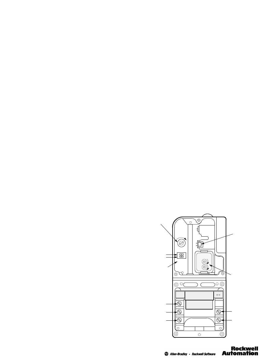
Series 5500 Type 42DRP Photohead and
42DTB Power Base with Covers Removed
Sensitivity
Adjustment
Light/Dark
Switch
Visible
Alignment
Indicator
Short Range
Long Range
Shutter
(on 42DRP
only)
PNP & NPN
Output
Circuitry
3
2
1
( + )
( - )
See page 7, for actual connection diagrams.
SENS
LO HI
DK LT
TWO - WAY
TIME DELAY
O
N
O
F
F
Low - High
Sensitivity
Switch