Input/output circuit and wiring – Rockwell Automation 45PVA Part Verification Array User Manual
Page 3
3
1. Job indicator mode (transmitted beam)
Either a steady light or flashing light mode can be selected.
Operating mode selection (retro/diffuse)
Retroreflective or diffuse operating mode can be selected
2. Job indicator speed control for flashing (transmitted beam)
The flashing speed can be selected as slow or fast.
Automatic sensitivity adjustment ON/OFF (retro/diffuse)
The automatic sensitivity adjustment can be turned on or off. (Regardless of this setting, sensitivity is always adjusted when
the power is turned on.)
3. Selectable operation mode (transmitted beam receiver)
The output mode of the receiver can be selected for light or dark operate.
Output Normally Open/Normally Closed (retro/diffuse)
The output mode can be selected for Normally Open or Normally Closed.
4. Selectable warning indicator
Select the warning indicator mode.
5. NPN/PNP selectable switch
Select the transistor mode for the output and the job indicator input.
NPN Output (PNP Input)
PNP Output (NPN Input)
6. Selectable frequency
The frequency can be switched to eliminate crosstalk.
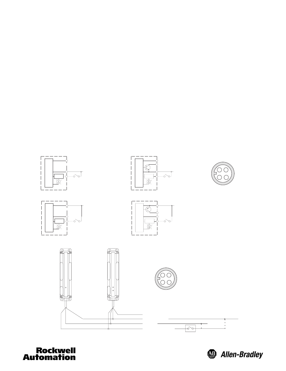
Input/Output Circuit and Wiring
The NPN/PNP input of the job indicator and the NPN/PNP output are selected by mode switch.
NPN Output
(selected)
Pin 1 (Brown): 12 to 24V DC
Job
Transmitter
Transmitted Beam Receiver and
Retroreflective/Diffuse
Pin 3 (Blue): 0V
Pin 2 (Pink or White):
Job Indicator Input
Pin 1 (Brown): 12 to 24V DC
Job
Pin 3 (Blue): 0V
Pin 2 (Pink or White):
Job Indicator Input
Pin 4 (Black): Output (NPN)
PNP Output
(selected)
Pin 1 (Brown): 12 to 24V DC
Job
Transmitter
Receiver
Pin 3 (Blue): 0V
Pin 2 (Pink or White):
Job Indicator Input
Pin 1 (Brown): 12 to 24V DC
Job
Pin 3 (Blue): 0V
Pin 2 (Pink or White):
Job Indicator Input
Pin 4 (Black): Output (PNP)
1
4
2
1
4
2
1
4
2
3
1
4
2
1
3
2
4
Face View Male Receptacle (Sensor)
DC Micro
Transmitter (not required for
Retroreflective/Diffuse models)
Transmitted Beam Receiver
and Retroreflective/Diffuse
Brown: 12 to 24V DC
Blue: 0V
White: Job Indicator Input
Black: Out
1
3
2
4
Face View Male Receptacle (Sensor)
DC Micro
1
4
3
2
(NPN Output
Selected)
(PNP Output
Selected)
Note: Warning light requires no wiring. It is triggered using internal logic when the input is off (low) and the target is present.