Step 3: remove the control assembly from the drive, Drives with phase i control, Remove the control assembly from the drive on – Rockwell Automation 20D Stegmann Feedback Option Board for PowerFlex 700S Drives User Manual
Page 6
6
Stegmann Feedback Option Board for PowerFlex® 700S Drives
Step 3: Remove the
Control Assembly from the
Drive
The steps to remove the control assembly from the drive are different for
drives with Phase I control versus drives with Phase II control. Refer to the
appropriate instructions:
•
Refer to
below.
•
Refer to
Drives with Phase II Control on page 7
Drives with Phase I Control
This step is necessary only when another drive or panel component blocks
access to the control assembly on frame 1 - 6 drives with Phase I control.
Avoid removing the control assembly if possible. If you do not need to
remove the control assembly from the drive, continue with Step 4:
the Feedback Option Board on page 9
.
Important: Before removing connections and wires, mark the connections
and wires to avoid incorrect wiring during assembly.
Continue with Step 4:
Remove the Feedback Option Board on page 9
.
Task
Description
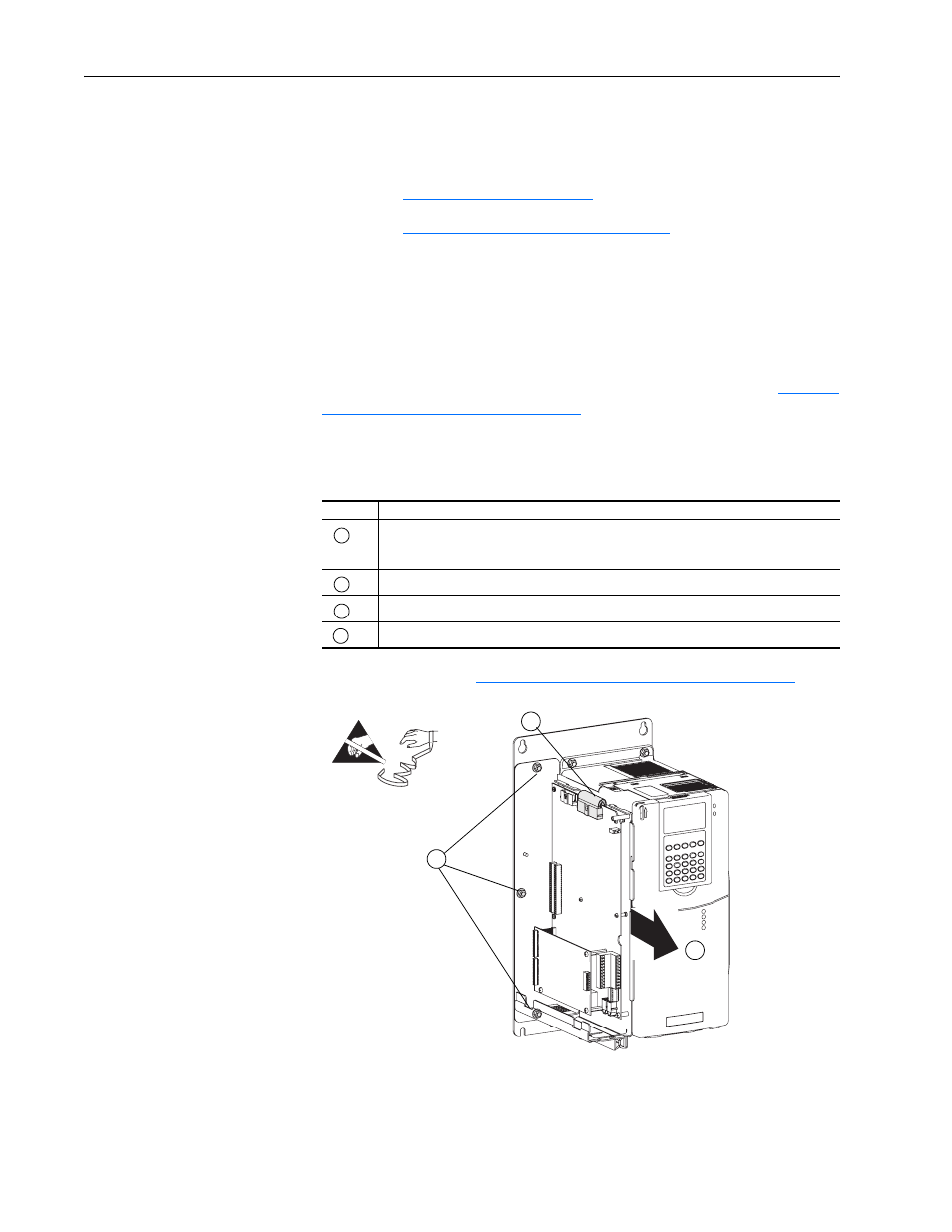
Unplug the I/O and SynchLink cables from the main control board, unplug feedback wiring
from the MDI Option board (if present), and unplug the communication cables from
DriveLogix controller (if present).
Unplug the ribbon cable.
Remove the three M5 nuts that secure the control assembly to the drive chassis.
Remove the control assembly from the drive.
A
B
C
D
B
C
D
Proper tightening
torque for reassembly
is 18 lb.•in.
=