Working principle, Standard materials, Connections – Thermal Transfer Systems M3-VG User Manual
Page 2: Technical data, Particulars required for quotation, Dimensions measurements (mm)
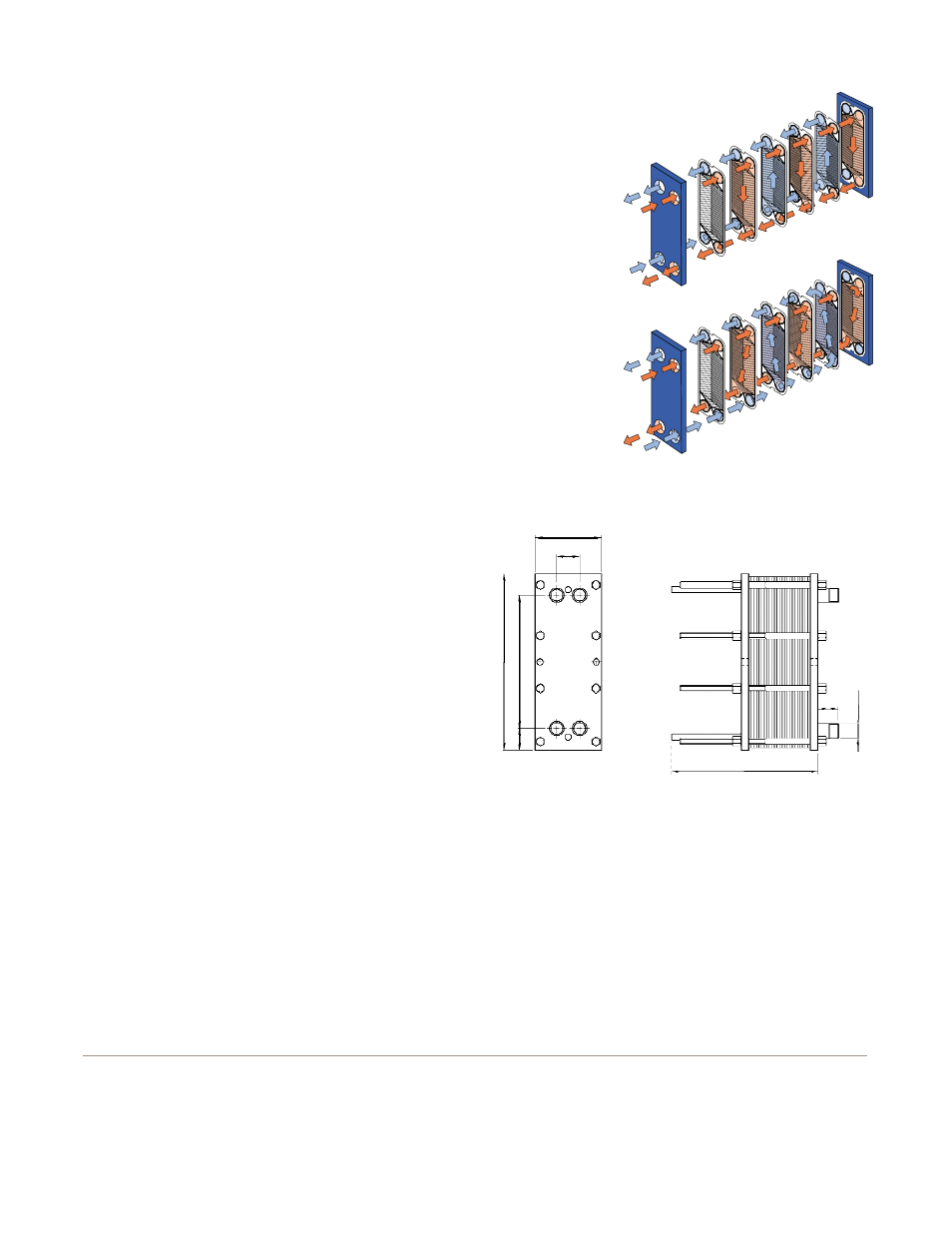
Working principle
Channels are formed between the plates and the corner ports
are arranged so that the two media flow through alternate
channels. The heat is transferred through the plate between
the channels, and complete counter-current flow is created
for highest possible efficiency. The corrugation of the
plates provides the passage between the plates, supports
each plate against the adjacent one and enhances
the turbulence, resulting in efficient heat transfer.
Standard materials
Frame plate
Mild steel, painted
Nozzles
Stainless steel AISI 316 or Titanium
Plates
Stainless steel AISI 316 or Titanium
Gaskets
M3
Nitrile, EPDM
M3X
Nitrile, EPDM, Viton
®
M3D
Nitrile, EPDM
Connections
1-
1
⁄
4
" NPT
Technical data
Mechanical design pressure (g)/temperature
VG
230 Psig/320ºF
FGL
230 Psig/320°F (non-ASME)
Maximum heat transfer surface
40 sq. ft
Particulars required for quotation
– Flow rates or heat load
– Temperature program
– Physical properties of liquids in question (if not water)
– Desired working pressure
– Maximum permitted pressure drop
– Available steam pressure
Dimensions
Measurements (mm)
The number of bolts may vary depending on pressure rating.
How to contact Alfa Laval
Contact details for all countries
are continually updated on our website.
Please visit www.alfalaval.com to
access the information directly.
ENSR00001USEN 0206
All rights reserved for changes in specifications
Flow principle of an M3
plate heat exchanger
Flow principle of an M3-X
plate heat exchanger
2-
1
⁄
2
"
7"
2-
3
⁄
8
"
19"
14"
7-
1
⁄
2
" – 19-
1
⁄
2
"
1-
1
⁄
4
"
THERMAL TRANSFER SYSTEMS, INC.
[email protected]
PH: 800-527-0131 FAX: 972-242-7568