Thermal Transfer Systems M3-VG User Manual
Page 12
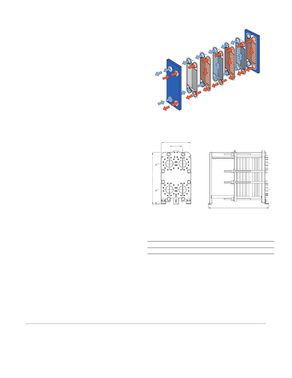
Working principle
Channels are formed between the plates and the corner ports
are arranged so that the two media flow through alternate
channels. The heat is transferred through the plate between
the channels, and complete counter-current flow is created
for highest possible efficiency. The corrugation of the plates
provides the passage between the plates, supports each
plate against the adjacent one and enhances the turbulence,
resulting in efficient heat transfer.
Standard materials
Frame plate
Mild steel, epoxy painted
Nozzles
Carbon steel
Metal lined: Stainless steel, Titanium
Plates
Stainless steel AISI 316 or Titanium
Gaskets
Nitrile, EPDM or HeatSeal F™
Connections
FG ASME
Size 8"
ANSI 150
FS ASME
Size 8"
ANSI 150/ANSI 300
Technical data
Mechanical design pressure (g)/temperature
FG ASME
150 psig /350°F
FS ASME
400 psig /320°F
*Frame FG also approved for 1.2 MPa /200°C to allow
use in steam systems without safety valves.
Maximum heat transfer surface
85 m
2
(910 sq. ft)
Particulars required for quotation
– Flow rates or heat load
– Temperature program
– Physical properties of liquids in question (if not water)
– Desired working pressure
– Maximum permitted pressure drop
– Available steam pressure
How to contact Alfa Laval
Contact details for all countries
are continually updated on our website.
Please visit www.alfalaval.com to
access the information directly.
PD 68200E1/0110
All rights reserved for changes in specifications
Flow principle of a plate heat exchanger
W
363
H
698
880-2715
Measurements (mm)
Type
H
W
H
TS20-MFG
1405
800
360
TS20-MFS
1435
800
390
Dimensions
THERMAL TRANSFER SYSTEMS, INC.
[email protected]
PH: 800-527-0131 FAX: 972-242-7568