Installation, Vertical termination – Regency Classic C34 Small Gas Stove User Manual
Page 24
24
Regency
®
CLASSIC C34-3 Direct Vent Freestanding Gas Stove
INSTALLATION
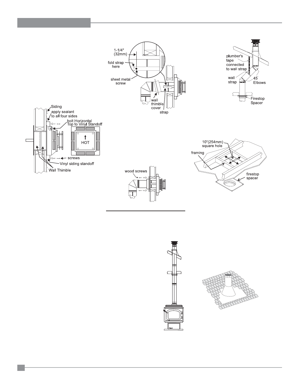
Diagram 9
the roof. Deter-
mine if ceiling
joists, roof raft-
ers or other fram-
ing will obstruct
the venting sys-
tem. You may
wish to relocate
t h e a p p l i -
a n c e o r
t o
offset, as shown
in diagram 9
t o
avoid cutting
load bearing
members.
3) To install the Round Support Box/Wall Thim-
ble in a fl at ceiling, cut a 10 inch square hole
in the ceiling centered on the hole drilled in
Step 2. Frame the hole as shown in diagram
Diagram 8
Diagram 10
VERTICAL
TERMINATION
Diagram 7
Diagram 6
Diagram 5
4) Attach the Vinyl Siding Standoff (if required)
to the Horizontal Vent Termination, but fi rst
run a bead of non-hardening mastic around
its outside edges, so as to make a seal
between vent cap and the standoff. Install
the Vinyl Siding Standoff between the vent
cap and the exterior wall and attach with the
four wood screws provided. Seal around
the Vinyl Siding Standoff on all four sides.
Diagram 5. The arrow on the vent cap
should be pointing up. Insure that the
1-1/4" clearances to combustible materials
are maintained. See diagram 5.
Note: If installing termination on a siding
covered wall, a vinyl siding standoff
or furring strips must be used to
ensure that the termination is not
recessed into the siding. The four
wood screws provided should be
replaced with appropriate fasteners
for stucco, brick, concrete, or other
types of sidings.
5) Before connecting the horizontal run of vent
pipe to the vent termination, slide the black
decorative wall thimble cover over the vent
pipe, then slide the Wall Thimble over the
vent pipe.
6) Slide the appliance and vent assembly
towards the wall carefully inserting the
vent pipe into the vent cap assembly. It is
important that the vent pipe extends into
the vent cap a suffi cient distance so as to
result in a minimum pipe overlap of 1-1/4
inches. Secure the connection between the
vent pipe and the vent cap by attaching the
two sheet metal strips extending from the
vent cap assembly into the outer wall of the
vent pipe. Use the two sheet metal screws
provided to connect the strips to the pipe
section. Bend any remaining portion of the
sheet metal strip back towards the vent cap,
so it will be concealed by the decorative wall
thimble cover. See diagram 6.
7) Install Wall Thimble in the center of the 10"
square and attach with wood screws (in
Canada).
8) Slide the decorative wall thimble up to the
wall surface being careful not to scratch the
paint and attach with screws provided. Apply
decorative brass or chrome trim if desired.
See diagram 7.
1) Maintain the 1-1/4" clearances
(air spaces) to combustibles
when passing through ceil-
ings, walls, roofs, enclosures,
attic rafter, or other nearby
combustible surfaces.
Do not pack air spaces with
insulation. Check "Venting
Arrangments" section for
the maximum vertical rise of
the venting system and the
maximum horizontal offset
limitations.
2) Set the gas appliance in
its desired location. Drop a
plumb bob down from the
ceiling to the position of the
appliance fl ue exit, and mark
the location where the vent
will penetrate the ceiling. Drill
a small hole at his point. Next,
drop a plumb bob from the roof
to the hole previously drilled in the ceiling, and
mark the spot where the vent will penetrate
Diagram 11: The upper half of the fl ashing is
installed under the roofi ng material and not
nailed down until the chimney is installed. This
allows for small adjustments.
10.
4) Assemble the desired lengths of black pipe
and elbows necessary to reach from the
appliance adaptor up though the Round
Support Box. Ensure that all pipes and el-
bow connections are in the fully twist-locked
position and sealed.
5) Cut a hole in the roof centered on the small
drilled hole placed in the roof in Step 2. The
hole should be of suffi cient size to meet
the minimum requirements for clearance
to combustibles of 1-1/4". Slip the fl ashing
under the shingles (shingles should overlap
half the fl ashing) as per diagram 11.
6) Continue to assemble pipe lengths.
Note: If an offset is necessary in the attic to
avoid obstructions, it is important to