Installation, Combustion and ventilation air, Clearances to combustibles – Regency Classic C34 Small Gas Stove User Manual
Page 10: Installation checklist, Locating your gas stove, Manufactured mobile home additional requirements
10
Regency
®
CLASSIC C34-3 Direct Vent Freestanding Gas Stove
INSTALLATION
COMBUSTION AND
VENTILATION AIR
The combustion air from this appliance is drawn
from outside the building through the outer
fl ue. Extra provision for combustion air is
not required.
CLEARANCES TO
COMBUSTIBLES
The clearances listed below are MINIMUM
distances. Measure the clearance to both the
appliance and the chimney connector. The
farthest distance is correct if the two clearances
do not coincide. For example, if the appliance
is set as indicated in one of the diagrams but
the back is too close, move the stove until the
correct clearance to the back is obtained.
This unit can be installed on a solid combustible
surface like a wood fl oor. This unit can also be
installed directly on carpeting or vinyl when the
bottom pedestal cover plate (provided with the
unit) is installed.
This appliance may be installed only with the
clearances as shown in the situations pictured.
Do not combine clearances from one type of
installation with another in order to achieve
closer clearances.
Use the minimum clearances shown in the
diagrams below:
INSTALLATION
CHECKLIST
1) Locate your appliance. Refer to the
following sections:
a. Locating Your Classic Gas Stove
b. Clearances to Combustibles
c. Venting. See "Exterior Vent Terminal
Locations" to " Venting Arrangments"
sections.
2) Install Optional Fan. Refer to "Optional Fan
Installation" section.
3) Assemble stove base - pedestal or bottom
shield and legs. Refer to "Pedestal
Assembly" or "Leg and Bottom Shield
Assembly" sections.
4) Choose a venting option and Install
accordingly. Refer to the following sections
where applicable:
a. DV Stove Horizontal Vent Kit
b. Dura-Vent Termination kits
c. Vent Restrictor setting
d. Converting CLass-A Metal Chimney or
Masonry Chimney to Direct Vent
System.
5) Make gas and electrical connections.
Refer to "Gas Connection" section. Test
the pilot. Must be as per diagram in "Pilot
Adjustment" section.
6) Test gas pressure. Refer to "Gas Pipe
Pressure Testing" section.
7) Install standard and optional features.
Refer to the following sections where
applicable:
a. Log Installation
b. Door and Glass Frame
c. Door Handle
d. Remote Control
e. Remote Wall switch
f. Wall Thermostat
8) Final check. Refer to "Final Check" section.
Before leaving this unit with the customer, the
installer must ensure that the appliance is fi r-
ing correctly and operation fully explained to
customer.
This includes:
1) Clocking the appliance to ensure the correct
fi ring rate (rate noted on label) after burning
appliance for 15 minutes.
2) If required, adjusting the primary air to ensure
that the fl ame does not carbon. First allow
the unit to burn for 15-20 min. to stabilize.
3) Check for proper draft.
CAUTION: Any alteration to the product that
causes sooting or carboning that results in dam-
age is not the responsibility of the manufacturer.
LOCATING YOUR
GAS STOVE
When selecting a location for your stove, ensure
that the clearances on this page are met as well
as ensuring that there is adequate accessibility
for servicing and proper operation.
For Vent Termination requirements, see "Exterior
Vent Terminal Locations" section.
MANUFACTURED
MOBILE HOME
ADDITIONAL
REQUIREMENTS
1) Ensure that structural members are not cut
or weakened during installation.
2) Ensure proper grounding using the #8
ground lug provided. See "Optional Fan
Installation" section.
3) Appliance must be anchored to the fl oor. See
"Pedestal Assembly" & "Leg and Bottom"
sections.
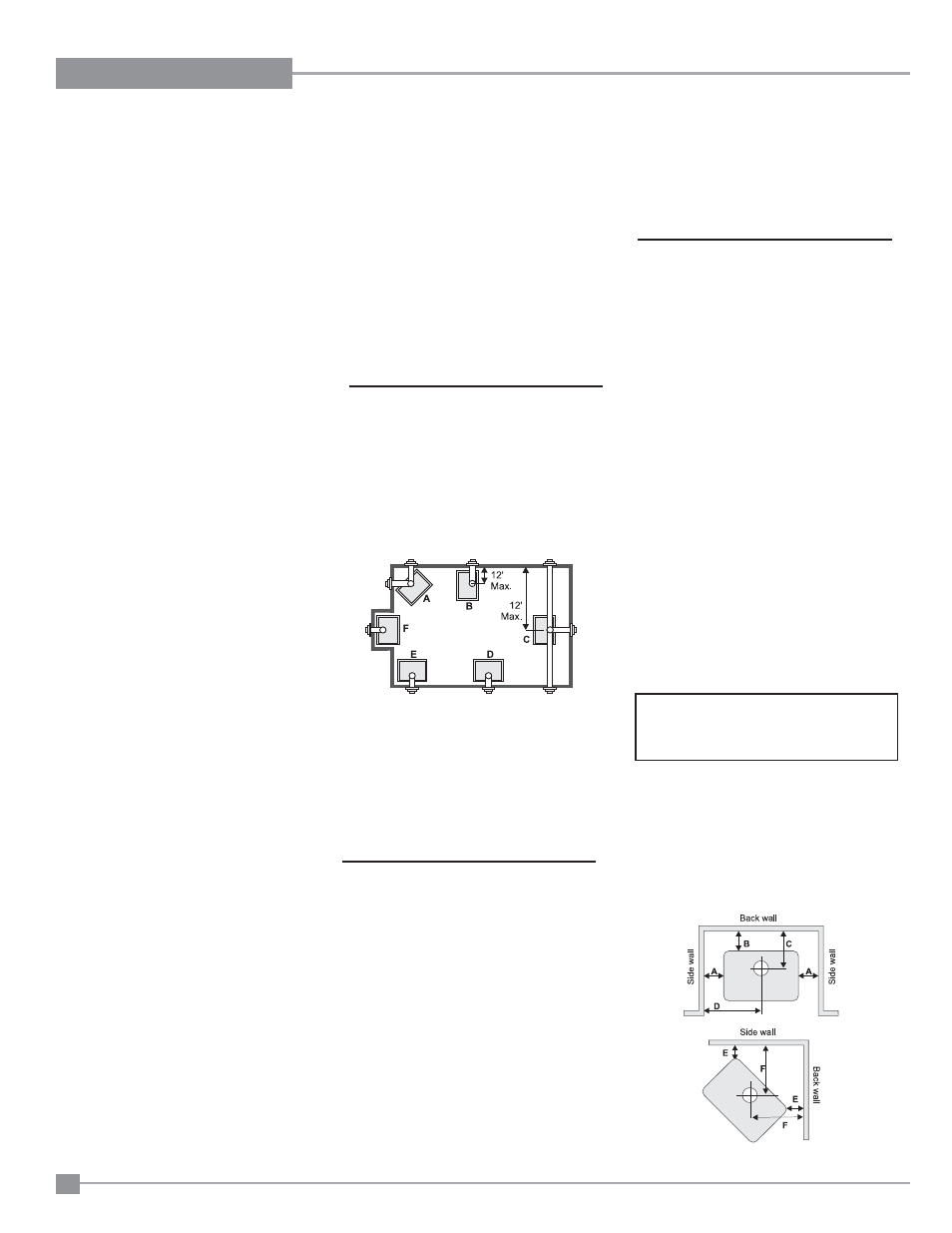
A) Cross
Corner
B) Room
Divider
C) Island
D) Flat on Wall
E)
Flat on Wall Corner
F)
Flush with Wall/Alcove
C34 Clearance to Combustibles
A Side Wall to Unit
10" / 250 mm
B Back Wall to Unit
6" / 150 mm
E Side Wall to Unit
1.5" / 38 mm
C34 Reference Dimensions
C Back Wall to Flue Centerline 13" / 330 mm
D Side Wall to Flue Centerline 22" / 559 mm
F Side Wall to Flue Centerline 14" / 356 mm
Minimum ceiling height is 36" / 914 mm from
top of unit.
Minimum clearance to vent 1-1/4" (32mm).