Installation, Pedestal assembly, Leg and bottom shield assembly – Regency Classic C34 Small Gas Stove User Manual
Page 12
12
Regency
®
CLASSIC C34-3 Direct Vent Freestanding Gas Stove
INSTALLATION
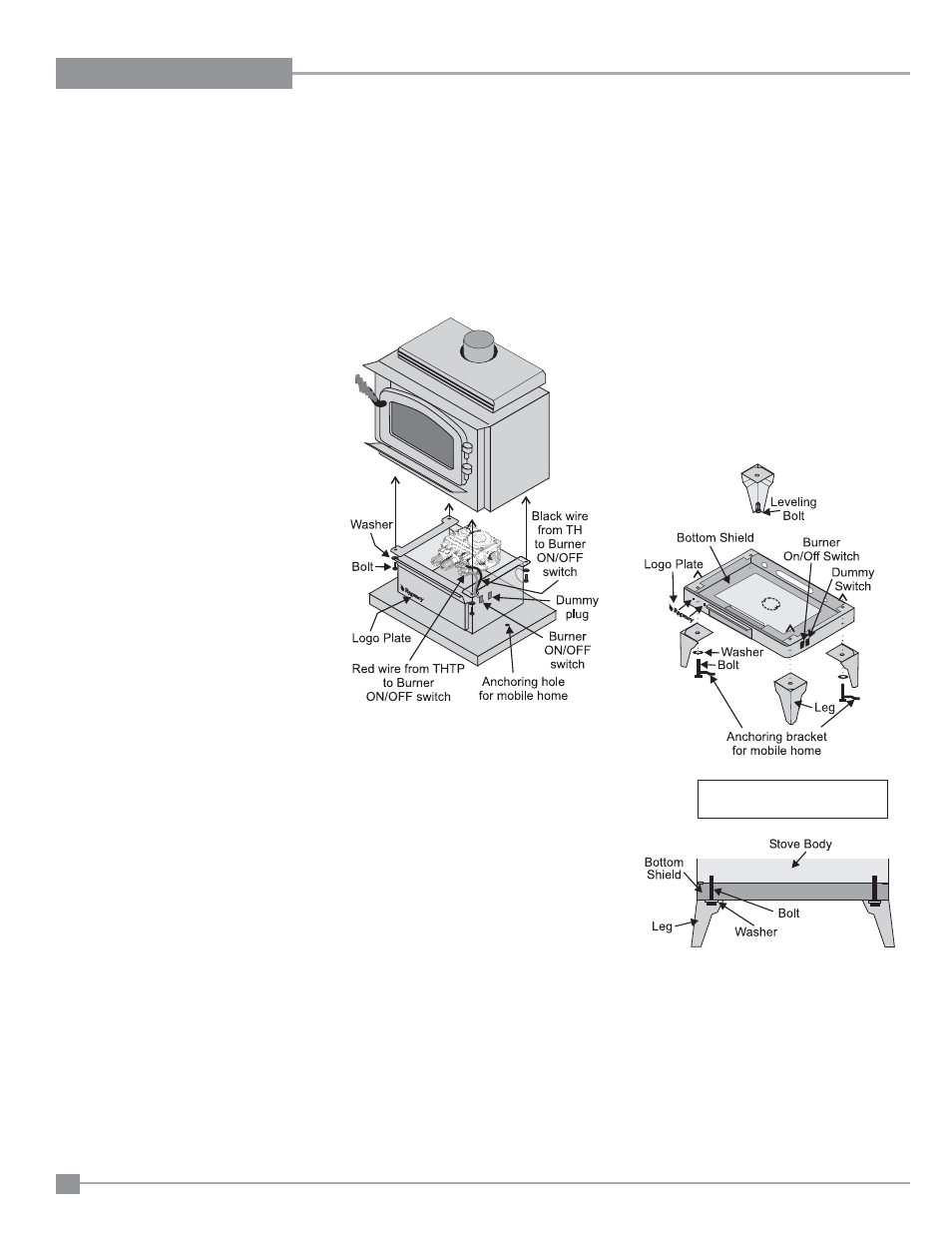
PEDESTAL ASSEMBLY
1) For easier assembly, tip the stove on its back
(preferably onto a soft surface to prevent
scratching).
2) Unscrew the 4 bolts in the underside of the
stove. Align the holes in the corners of the
pedestal top with the corresponding holes in
the base of the stove. Use washers which
are supplied with the pedestal as shown in
diagram. Reinstall bolts.
Anchoring Brackets Hold Down
Package Part# 846-585
10) Put the insulation gasket on the back of
the fan. Line up the keyhole slots with the
matching screws and pull back slightly to
lock into place. While holding fan assembly
in place, tighten screws.
11) Remove the dummy plug from the right side
of the bottom shield or pedestal and install
the supplied fan switch.
12) Attach the hot wire from power cord to the
thermodisc.
13) Slide thermodisc under the thermodisc
bracket.
14) Connecting wires to the 3 way switch:
a. Connect the red wire from the fan to the
top of the 3 way switch.
b. Connect black wire from fan to the bottom
of the 3 way switch.
c. Connect white jumper wire to middle of
the three way switch. See wiring diagram
below.
15) Connect white wire from fan motor to neutral
on the power cord.
16) Pull power wire back and put strain relief
grommet in place as per diagram 4.
17) Reverse steps 3-1 to complete installation.
Fan Removal
1) Disconnect the power to the fan.
2) Allow the stove to cool to room tempera-
ture.
3) Open the pedestal door and remove the
screws on the door cover plate. (Leg units:
remove the bottom access panel.)
4) Loosen the screws of the nutserts.
5) Remove the fan assembly from the key slots
at the fan base and pull fan out through the
rectangular opening. (Diagram 3).
6) Turn fan 90 degrees. (Diagram 2). (Pedestal
units only).
7) Disconnect the green ground wires to the
grounding lug.
8) Disconnect the white wire of the fan from
the power cord.
9) Disconnect the red wire and black wire (from
fan to Fan Switch).
10) Take fan out from the stove body. (Diagram
1).
LEG AND BOTTOM
SHIELD ASSEMBLY
These instructions apply to the steel leg, painted
cast leg and the gold plated cast leg. It will be
easier to attach the legs to the stove if it is
tipped on its back (preferably on a soft surface
to prevent scratching).
1) Remove the 4 bolts in the underside of the
base and discard.
2) Slide the bolt and washer (supplied with the
bottom shield) through the leg, then slide
the bottom shield in between the leg and
the base of the stove. Tighten the bolts.
3) Hook up the Burner ON/OFF switch.
4) Level the stove by adjusting the levelling
bolts in the bottom of each leg.
3) Hook up wires to Burner ON/OFF switch
and valve assembly (be careful not to pinch
wires). See diagram above.
4) Push the Regency
®
logo into the two holes
in the front bottom left corner of the pedestal
cover plate.
Note: Any paint touch up should be done
prior to placing logo on pedestal.