Control unit, Circuit diagram td70.c hp, Service manual td70.c 24 – Summit TDC111V Service Manual User Manual
Page 24
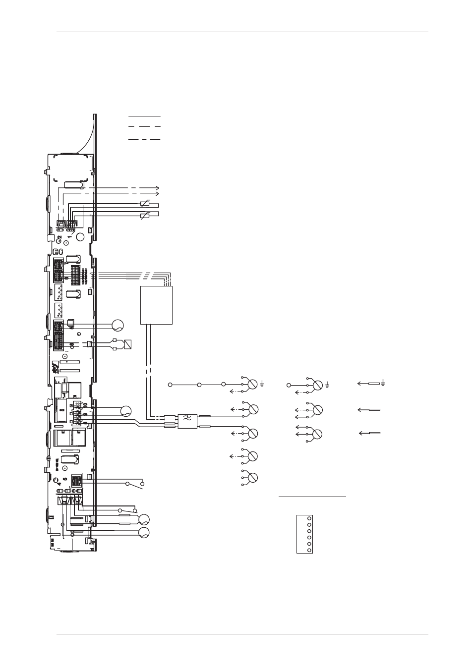
Circuit diagram TD70.C HP
Control unit
WIRES IN SOME MACHINES
INTERNAL CONNECTION
NTC 1
F
AP
DB
FB
N
L1
L3
L2
CM6
CM5
CM3
INKB
CM2
MO
CM4
CM1
NTC 2
WIRES IN ALL MACHINES
CABLE POSITIONS
1: THERMISTOR
2:
COINMETER
4: MOTOR, DRAIN PUMP, FLOAT SWITCH
5: DOOR SWITCH
6: COMMUNICATIONS INTERFACE
8: POWER
9: HEATING ELEMENT
CI
F1
F2
3 Phase, 10 A
N
L1
CM6
CM3
INKB
1 Phase, 10A
No coin meter
F1
F2
CO
CM5
SV
PHASE
BLACK
CM1
CM2
BROWN
CM5
CM4
CM3
GROUND
BLUE
CM6
BLACK
BLUE
YELLOW-
GREEN
FROM CONTROL UNIT
NEUTRAL
FROM CONTROL UNIT
If coin meter is selected CM1
and CM4 needs to be closed to
start the machine
(default closed with jumper)
CONNECTOR FOR COIN METER
PHASE
FA
L
N
MO
CO
MO
F1
F2
1 Phase, 10A
Service Manual TD70.C
24
This manual is related to the following products: