Salsbury Industries 95000 Series Plastic Lockers (95168,95368 Five Tier) User Manual
Page 3
Plastic Lockers – 95000 Series
Models 95168 & 95368 Five Tier
Assembly Instructions
SALSBURY INDUSTRIES
1010 East 62
nd
Street, Los Angeles, CA 90001-1598
Phone: 1-800-562-5377 Int’l Phone: 323-846-6700
Fax: 1-800-562-5399 Int’l Fax: 323-846-6800
www.lockers.com engineering
@
lockers.com
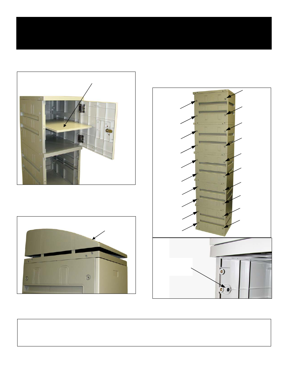
Step 11. Slide the shelves (optional) into the slots in the locker side
panels. There is one slot available for a shelf in each of the five (5)
compartments.
Step 14. If two (2) or more lockers are to be installed side by side,
the lockers should be fastened together with the four (4) nuts and
long screws provided. Select any two (2) holes toward the front and
any two (2) holes toward the rear. The illustration below shows the
20 holes that are available. The lower illustration shows the inside
view of a hole and screw.
Installation instructions are provided as general guidelines. It is advised that a professional installer be consulted. Salsbury Industries assumes no product assembly or installation liability.
Copyright © 2010 Salsbury Industries. All rights reserved. (Rev. 02, 7/22/2010) Page 3 of 3
Step 12. Install the sloping hood (optional) to the top of each locker
column by aligning six (6) locating tabs with the topmost panel.
Press locating tabs into place. Illustration shows sloping hood before
pressing tabs into place. Plastic filler strips shown in step 6 are not
required on units with a sloping hood and can be discarded.
SLOPING
HOOD
SHELF
INSIDE VIEW
OF HOLE
AND SCREW
Step 13. Install placards (optional) in the indentation near the top of
each door.
The assembly of the plastic lockers is now complete.