Salsbury Industries 95000 Series Plastic Lockers (95168,95368 Five Tier) User Manual
Page 2
Plastic Lockers – 95000 Series
Models 95168 & 95368 Five Tier
Assembly Instructions
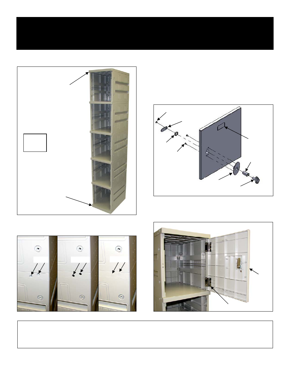
Step 7. Stack the four (4) upper units onto the lower unit. Press all
units firmly together. Use a mallet if necessary.
SALSBURY INDUSTRIES
1010 East 62
nd
Street, Los Angeles, CA 90001-1598
Phone: 1-800-562-5377 Int’l Phone: 323-846-6700
Fax: 1-800-562-5399 Int’l Fax: 323-846-6800
www.lockers.com engineering
@
lockers.com
Installation instructions are provided as general guidelines. It is advised that a professional installer be consulted. Salsbury Industries assumes no product assembly or installation liability.
Copyright © 2010 Salsbury Industries. All rights reserved. (Rev. 02, 7/22/2010) Page 2 of 3
Step 8. Install screws and hole covers where side panels join to top
panels and base panel. There are 22 screws and hole covers on
each of the two sides of the assembly (44 in total).
Step 9. Attach the plastic oval lock plate to the front of the five (5)
doors with two (2) screws from the rear of the door. Insert the
stainless steel hasp through hole in front of doors making sure cutout
is facing downward. Secure by threading nut provided onto it from
rear. Insert lock knob through hasp from front of door making sure
hole in lock knob is facing downward. Attach cam to rear of lock
knob shaft with screw provided. Be sure the cam is pointing toward
the outside of the door and is properly engaged with the square shaft
end of the lock knob.
PANEL WITH
FILLER STRIPS
(IF NO OPTIONAL
SLOPING HOOD)
SCREW
Step 10. Fasten the ten (10) hinges (two (2) for each of the five (5)
doors) provided in the hardware package securely to each hinge
position with the screws provided as shown below. Fasten each of
the five (5) doors to the appropriate pair of hinges.
BASE PANEL
(THICKER)
CAM
LOCK
PLATE
HASP
LOCK
KNOB
NUT
ALL
UNITS
STACKED
SCREWS
(2)
NAMEPLATE
(OPTIONAL)
COVERS
HOLES
SCREWS
DOOR
HINGE