Set up instructions – MacDon DWA for M Series User Manual
Page 12
SET UP INSTRUCTIONS
169216
Revision
E
10
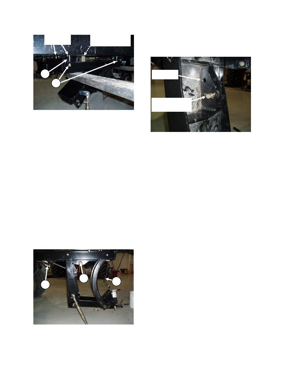
8. Support linkage assembly with a forklift.
NOTE: Make sure fork is not lifting against
cylinder fitting.
9. M150/M155/M200: Align linkage with four
bolts in windrower frame. Locate in
hardware kit two spacers (S), 1-1/2 in. OD x
1 in. ID x 2-3/4 in. long. Mount linkage in the
most forward position (as shown) if used
with an R-Series Disc Header and mount in
the most rearward position if used with
A-Series Auger Header or D-Series Draper
Header. Position spacers (S) on rear bolts
and install four flat washers, lock washers
and nuts at (K) and tighten.
10. M205: Align linkage with four bolts in
windrower frame. Mount linkage in the most
forward position (as shown) if used with an
R-Series Disc Header and mount in the
most rearward position if used with A-Series
Auger Header or D-Series Draper Header.
Install four flat washers, lock washers and
nuts at (K) and tighten.
11. Lower linkage by hand by first pulling on
safety pin (M) on the LH side of linkage.
Remove plugs at end of lift cylinder hoses
(L) if needed to remove air from hoses.
12. Cylinder pivot must be in the lower hole
(shown) for A-Series Auger or D-Series
Draper Headers and upper hole for R-Series
Rotary Disc Headers. Move pin to upper
hole if used with R-Series Rotary Disc
Header.
L
L
M
R-Series
Disc Header
A-Series Auger
& D-Series Draper
Headers
K
R-Series
Disc Header
Mounting
A-Series Auger
& D-Series Draper
Headers Mounting
S