B. assembly for use as an arduino shield – Pololu Dual VNH5019 User Manual
Page 7
3.b. Assembly for Use as an Arduino Shield
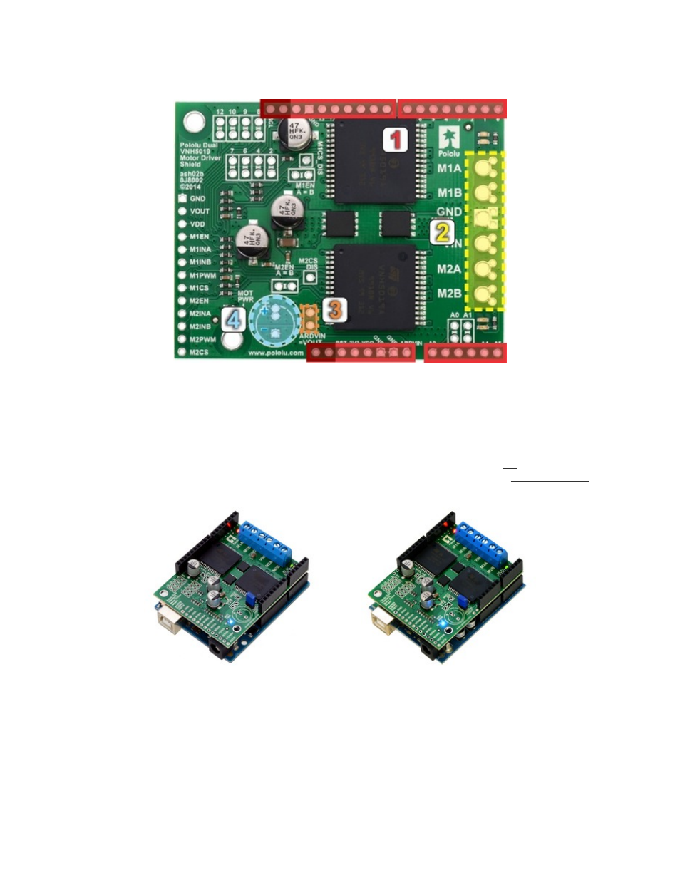
1. Stackable Arduino headers: Before you can use this board as an Arduino shield, you need to solder four
of the five included Arduino header strips to the set of holes highlighted in red in the picture above. The headers
should be oriented so that the female sockets rest on the top side of the shield and face up while the male pins
protrude down through the board, and the solder connections should be made on the underside of the shield. The
newest Arduino boards, including the Uno R3 and the Leonardo, use one 10×1 header, two 8×1 headers, and one
6×1 header, as shown in the left picture below; older Arduino boards use two 8×1 headers and two 6×1 headers,
as shown in the right picture below (the two pairs of pins highlighted in darker red should not be populated if
you are using this board with an older Arduino that does not support these additional pins). Please make sure
you solder the appropriate headers for your particular Arduino!
2. Motor and power connections: The six large holes/twelve small holes on the right side of the board,
highlighted in yellow in the above diagram, are the motor outputs and power inputs. You can optionally solder
the included 5mm-pitch terminal blocks to the six large holes to enable temporary motor and motor power
connections, or you can break off a 12×1 section of the included 0.1″ header strip and solder it into the smaller
through-holes that border the six large motor and motor power pads. Note, however, that the terminal blocks are
only rated for 16 A, and each header pin pair is only rated for a combined 6 A, so for higher-current applications,
Pololu Dual VNH5019 Motor Driver Shield User’s Guide
© 2001–2014 Pololu Corporation
3. Getting Started with an Arduino
Page 7 of 28