Using as a general-purpose motor driver, Section 4 – Pololu Dual VNH5019 User Manual
Page 15
4. Using as a General-Purpose Motor Driver
The set of pins along the left side of the shield provides direct access to the VNH5019 motor drivers, which means
this board can be used as a general-purpose motor driver controlled by devices other than Arduinos. This section
explains how to use the dual VNH5019 motor driver shield this way and provides some basic information about the
motor driver pins to help get you started. However, we strongly encourage you to consult the
(629k pdf) for detailed pin descriptions, truth tables,
and electrical characteristics. This shield is essentially a breakout board for two VNH5019 motor driver ICs, so the
datasheet is your best resource for answering questions not covered by this user’s guide.
4.a. Assembly for Use as a General-Purpose Motor Driver
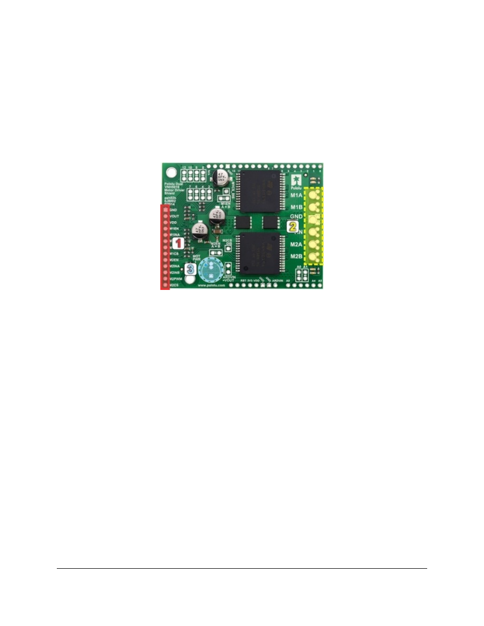
1. Logic connections: The 13 small holes along the left side of the board, highlighted in red in the above
diagram, are used to interface with the motor drivers. You can optionally solder a 13×1 piece of the included
0.1″ male header strip to these pins. Soldering the pins so they protrude down allows the logic side of the motor
driver to be plugged into a standard
or perfboard. You can also solder
or custom connectors to these pins.
2. Motor and power connections: The six large holes/twelve small holes on the right side of the board,
highlighted in yellow in the above diagram, are the motor outputs and power inputs. You can optionally solder
the included 5mm-pitch terminal blocks to the board to enable temporary motor and motor power connections,
or you can break off an 12×1 section of the included 0.1″ header strip and solder it into the smaller through-holes
that border the six large motor and motor power pads. Note, however, that the terminal blocks are only rated for
16 A, and each header pin pair is only rated for a combined 6 A, so for higher-current applications, thick wires
with
should be soldered directly to the board.
3. Additional power capacitor: The motor driver shield includes three pre-installed 47 uF electrolytic power
capacitors, and there is space—highlighted in blue in the above picture—to add an additional capacitor (e.g. to
compensate for long power wires or increase stability of the power supply). An additional power capacitor is
usually not necessary, and no additional capacitors are included with this shield.
With the exception of the pins labeled “MxEN A=B” and “MxCS_DIS”, all of the through-holes not highlighted in the
above diagram are only relevant when using this driver as an Arduino shield. The “MxEN A=B” and “MxCS_DIS”
pins are explained in the “Pinout” portion of
, but they will not be needed in typical applications and can
generally be ignored.
Pololu Dual VNH5019 Motor Driver Shield User’s Guide
© 2001–2014 Pololu Corporation
4. Using as a General-Purpose Motor Driver
Page 15 of 28