B. signal connections, Section 3.b ) – Pololu TReX Jr User Manual
Page 6
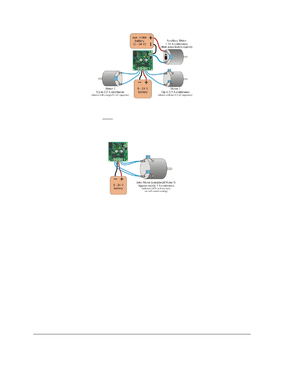
TReX Jr motor connections (separate battery for the auxiliary motor)
It is possible to power the auxiliary motor with a second, separate 0 – 24 V battery, as shown above. To do so,
connect that battery’s ground to the upper of the two auxiliary motor connection block ports. Connect one of your
auxiliary motor’s leads to the lower connection block port and connect the other of your motor’s leads directly to the
battery’s positive side. You will still need to solder a diode across your auxiliary motor’s terminals.
Option 3:
TReX Jr joint-motor connection
Lastly, you can use both motor 1 and 2 outputs to control a single, more powerful (up to 5 A continuous)
bidirectional motor by connecting it as shown above. One of the motor’s terminals connects to both of motor 1’s
outputs while the other of the motor’s terminals connects to both of motor 2’s outputs. In order to use your TReX Jr
in this way, you must use the serial interface to set the TReX Jr to “joint motor mode”. In this mode, the single
bidirectional motor is considered “motor 1”. The motor speed/direction indicator LEDs will not work in this mode,
nor will current sensing or channel mixing. Although it is not shown in the figure above, you can additionally
control an auxiliary motor while running in “joint motor mode”.
3.b. Signal Connections
RC/analog signals should connect to the interior of the three channel columns; this connection is represented by the
white wire in the figure below.
The middle column is connected to the TReX Jr’s regulated power (Vcc) through the Battery Elimination Circuit
(BEC) jumper and will provide 5 V to your RC receiver or analog controller when this jumper in place. This
connection is represented by the red wire in the figure below. If you want to power your RC receiver or analog
controller from a source other than the TReX Jr, make sure you remove the BEC jumper.
Pololu TReX Jr User's Guide
© 2001–2009 Pololu Corporation
3. Getting Started
Page 6 of 23