Getting started, A. motor and power connections – Pololu TReX Jr User Manual
Page 4
3. Getting Started
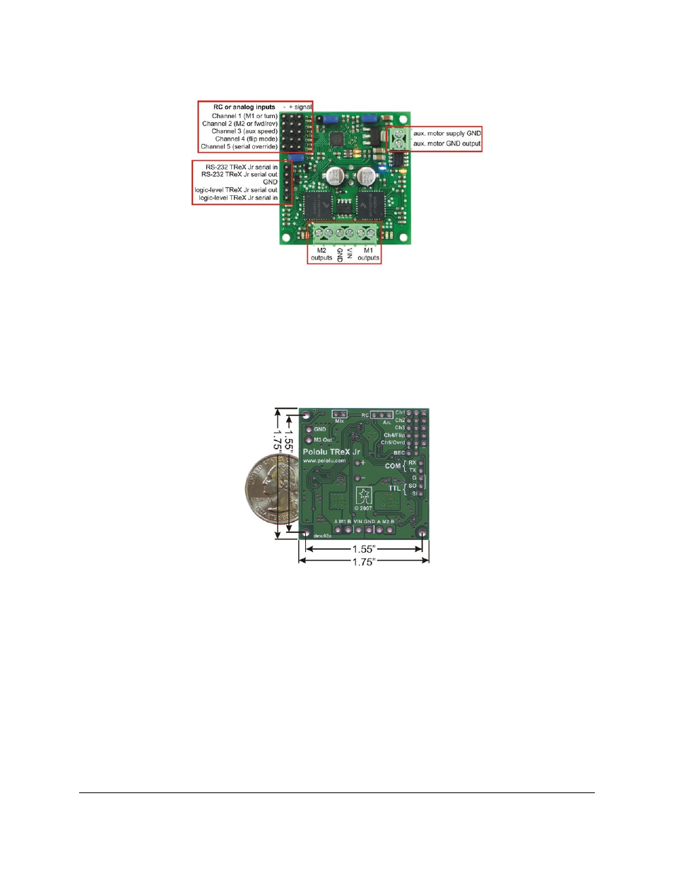
TReX Jr input/output connection points
Getting started with your TReX Jr can be as simple as connecting power, your motors, and your RC or analog
control signals (see Section 3.a and Section 3.b). Configure your jumpers for RC or analog mode (see Section 3.c)
and you’re good to go. While it’s running, the TReX Jr will communicate with you via its LEDs (see Section 3.d).
Once you have all your connections in place, we recommend your first step be to calibrate your TReX Jr for your
particular RC or analog controller (see Section 3.e).
Pololu TReX Jr Dual Motor Controller bottom view with dimensions
3.a. Motor and Power Connections
The TReX Jr receives its power through the VIN/GND connector terminals. VIN should be between 5 and 24 V and
your power source must be able to supply the current your motors will be drawing. The TReX Jr can supply peaks of
5 A and up to a continuous 2.5 A to each of its two bidirectional motors. Performance will depend the on actual
system and its ability to dissipate heat. The TReX Jr is designed to help heat flow along the board away from the
MC33887 motor driver chips, but addition of a heat sink and good air flow will further improve performance. The
TReX Jr can supply up to 10 A (continuous) to the auxiliary motor.
Pololu TReX Jr User's Guide
© 2001–2009 Pololu Corporation
3. Getting Started
Page 4 of 23