Pololu TReX Jr User Manual
Page 5
Note: The TReX Jr uses a linear voltage regulator to obtain its logic voltage (5-V Vcc). If you supply a
VIN of 24 V, your Vcc line will be limited to a maximum of 50 mA because of the regulator’s 1-W power
dissipation rating. This limitation might prevent your TReX Jr from being able to safely power an RC
receiver when VIN is so much higher than Vcc.
There are several different ways to connect motors to your TReX Jr:
Option 1:
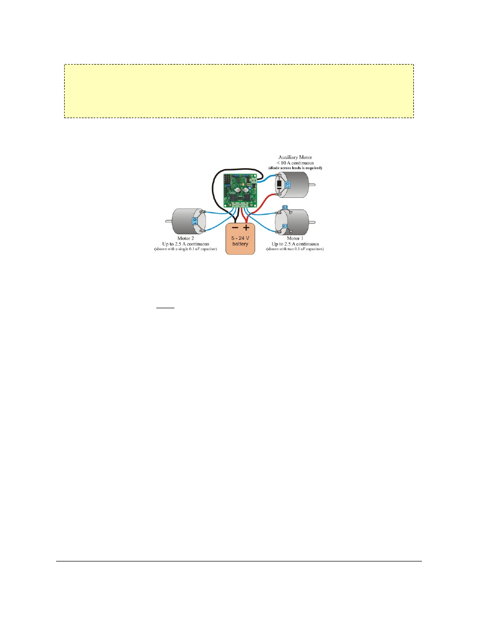
TReX Jr motor connections (single battery)
The figure above demonstrates how to connect two bidirectional motors and a unidirectional auxiliary motor to your
TReX Jr, all powered by the same battery. Note that the auxiliary motor is driven by permanently connecting one
lead to power while the board PWMs the other lead between high impedance and ground. You must connect your
battery’s ground directly to the upper port of the auxiliary motor’s connection block if you plan to use the auxiliary
motor. Otherwise, the auxiliary motor could attempt to pull too much current through the TReX Jr itself, thereby
damaging the unit.
The auxiliary motor’s other lead connects to the lower port of its connection block. You will need to connect a diode
across the auxiliary motor’s terminals as shown below. Failing to do so will adversely affect the performance of
your TReX Jr and could result in permanent damage to the device. Take great care to ensure you do not solder the
diode in backwards! You should not solder a diode to your bidirectional motors.
You may find it beneficial to solder 0.1uF capacitors across all of your motors’ terminals. This will decrease the
noise put out by your motors and can improve performance of your TReX Jr. You can further decrease the noise put
out by your motors by keeping their leads as short as possible and twisting them around each other in a helix.
Option 2:
Pololu TReX Jr User's Guide
© 2001–2009 Pololu Corporation
3. Getting Started
Page 5 of 23