Overview, Control unit installation, Site layout examples – Paxton Net2 plus control unit User Manual
Page 2
Page
2
A Net2 plus can connect to the Net2 PC using either an un-shielded RJ45 patch cable or an RS485 data line. This
greatly increases the number of installation options available to the installer.
One Net2 plus can also be used as the TCP/IP interface for an RS485 daisy chain of Net2 plus and Net2 classic units.
When used with a TCP/IP connection, it must first be detected using the Net2 Server Configuration Utility. See later
section of this instruction and
AN1006 - Installing remote sites using TCP/IP <
http://paxton.info/51 >
When used with an RS485 data line, on-board termination resistors can be put in circuit with a simple slide switch.
Ensure that units installed in the middle of the data line have this switch turned OFF.
A dedicated Intruder Alarm connection is provided.
Overview
The TCP/IP interface allows an RS485 data line to be controlled by the Net2 Server running across a LAN network.
An RS485 data line has a 1 km maximum length. This distance can be increased by using Paxton high speed
repeaters or by using shorter independant data lines using multiple LAN connections controlled from the same PC.
Control unit installation
Wire the components to the Access Control Unit (ACU) as shown on the first page. Power up the unit and wait for
the OK heartbeat.
Press the exit button or in the absence of an exit button, short the 0V and exit terminals together. The lock relay
LED will come on and the lock should release.
The reader's default indication has all the LED's on. Access granted is denoted with a single flashing Green LED.
Access Denied is a single flashing Red LED.
Site Layout Examples
1
r
ed
ae
R
:
n
oi
t
ua
C
yl
no
s
re
da
er
C
D
V2
1
ro
F
2
r
ed
ae
R
12V
Red LED
Amber LED
Green LED
Data/D0
Clock/D1
Media Detect
0V
12V
Red LED
Amber LED
Green LED
Data/D0
Clock/D1
Media Detect
0V
N.C.
N.O.
COM
N.C.
N.O.
COM
Alarm
12V
Green LED
Exit
0V
st
up
nI
tputsu
O
re
o
0V
12V
Contact
0V
0V
amper
re
p
ma
/
tc
at
no
C
no
tt
u
ti
xE
2
yal
e
R
1
yal
e
R
Expansion
Rx
x
R
Net ork
CA
Cable Codin
nr
G/
t
e
ra
ps
r
o
ne
er
c
a
ta
d
mo
r
s
er
oc
el
ba
c
ne
er
G
nr
O/
t
e
na
r
O
10/100 Et ernet
er er Connected
er er Link 100
10
End o Line ermination
ON
OFF
Net2 plus
LACE ERIAL
N M ER
LA EL ERE
Intruder Alarm
et
V0
mr
A
es
ne
M
O
C
.
O.
N
Red 12v dc
Brown
Orange
Green
Yellow
Blue
Mauve
Black/White
Brown
Yellow
Reader 1
Orange
Keypad 1
+12v
0v
N.C.
N.O.
Com
N.C.
N.O.
Com
Alarm Output
0v
Contact
0v
Exit
0v
Tamper
PSU
Rx
Tx
Relay 1
Relay 2
Exit
Contact
Tamper
PSU
OK
5v
12v
Red
Br
own
Orange
Gr
een
Yellow
Blue
Mauve
Black/White
Br
own
Yellow
Orange
Reader 2
Keypad 2
Power
Relay 1
Relay 2
Inputs
Network
CA
T5 cable coding
White/Green
Green
White/Orange
Orange
1
2
3
4
Screen or spare cores
from network cable
CAUTION: for 12v d.c. r
eaders only
. For
corr
ect connection of old 5v r
eaders, r
efer to
instructions.
Serial number
241821
Test ID: 012345678901
z-1440
3
2
4
8
9
8
0
0
0
0
0
4
RS485 data line
Net2 plus
Net2 classic
1
r
ed
ae
R
:
n
oi
t
ua
C
yl
no
s
re
da
er
C
D
V2
1
ro
F
2
r
ed
ae
R
12V
Red LED
Amber LED
Green LED
Data/D0
Clock/D1
Media Detect
0V
12V
Red LED
Amber LED
Green LED
Data/D0
Clock/D1
Media Detect
0V
N.C.
N.O.
COM
N.C.
N.O.
COM
Alarm
12V
Green LED
Exit
0V
st
up
nI
tputsu
O
re
o
0V
12V
Contact
0V
0V
amper
re
p
ma
/
tc
at
no
C
no
tt
u
ti
xE
2
yal
e
R
1
yal
e
R
Expansion
Rx
x
R
Net ork
CA
Cable Codin
nr
G/
t
e
ra
ps
r
o
ne
er
c
a
ta
d
mo
r
s
er
oc
el
ba
c
ne
er
G
nr
O/
t
e
na
r
O
10/100 Et ernet
er er Connected
er er Link 100
10
End o Line ermination
ON
OFF
Net2 plus
LACE ERIAL
N M ER
LA EL ERE
Intruder Alarm
et
V0
mr
A
es
ne
M
O
C
.
O.
N
RS485 data line
Net2 plus
1
r
ed
ae
R
:
n
oi
t
ua
C
yl
no
s
re
da
er
C
D
V2
1
ro
F
2
r
ed
ae
R
12V
Red LED
Amber LED
Green LED
Data/D0
Clock/D1
Media Detect
0V
12V
Red LED
Amber LED
Green LED
Data/D0
Clock/D1
Media Detect
0V
N.C.
N.O.
COM
N.C.
N.O.
COM
Alarm
12V
Green LED
Exit
0V
st
up
nI
tputsu
O
re
o
0V
12V
Contact
0V
0V
amper
re
p
ma
/
tc
at
no
C
no
tt
u
ti
xE
2
yal
e
R
1
yal
e
R
Expansion
Rx
x
R
Net ork
CA
Cable Codin
nr
G/
t
e
ra
ps
r
o
ne
er
c
a
ta
d
mo
r
s
er
oc
el
ba
c
ne
er
G
nr
O/
t
e
na
r
O
10/100 Et ernet
er er Connected
er er Link 100
10
End o Line ermination
ON
OFF
Net2 plus
LACE ERIAL
N M ER
LA EL ERE
Intruder Alarm
et
V0
mr
A
es
ne
M
O
C
.
O.
N
1
r
ed
ae
R
:
n
oi
t
ua
C
yl
no
s
re
da
er
C
D
V2
1
ro
F
2
r
ed
ae
R
12V
Red LED
Amber LED
Green LED
Data/D0
Clock/D1
Media Detect
0V
12V
Red LED
Amber LED
Green LED
Data/D0
Clock/D1
Media Detect
0V
N.C.
N.O.
COM
N.C.
N.O.
COM
Alarm
12V
Green LED
Exit
0V
st
up
nI
tputsu
O
re
o
0V
12V
Contact
0V
0V
amper
re
p
ma
/
tc
at
no
C
no
tt
u
ti
xE
2
yal
e
R
1
yal
e
R
Expansion
Rx
x
R
Net ork
CA
Cable Codin
nr
G/
t
e
ra
ps
r
o
ne
er
c
a
ta
d
mo
r
s
er
oc
el
ba
c
ne
er
G
nr
O/
t
e
na
r
O
10/100 Et ernet
er er Connected
er er Link 100
10
End o Line ermination
ON
OFF
Net2 plus
LACE ERIAL
N M ER
LA EL ERE
Intruder Alarm
et
V0
mr
A
es
ne
M
O
C
.
O.
N
Net2 plus
Net2 plus
1
r
ed
ae
R
:
n
oi
t
ua
C
yl
no
s
re
da
er
C
D
V2
1
ro
F
2
r
ed
ae
R
12V
Red LED
Amber LED
Green LED
Data/D0
Clock/D1
Media Detect
0V
12V
Red LED
Amber LED
Green LED
Data/D0
Clock/D1
Media Detect
0V
N.C.
N.O.
COM
N.C.
N.O.
COM
Alarm
12V
Green LED
Exit
0V
st
up
nI
tputsu
O
re
o
0V
12V
Contact
0V
0V
amper
re
p
ma
/
tc
at
no
C
no
tt
u
ti
xE
2
yal
e
R
1
yal
e
R
Expansion
Rx
x
R
Net ork
CA
Cable Codin
nr
G/
t
e
ra
ps
r
o
ne
er
c
a
ta
d
mo
r
s
er
oc
el
ba
c
ne
er
G
nr
O/
t
e
na
r
O
10/100 Et ernet
er er Connected
er er Link 100
10
End o Line ermination
ON
OFF
Net2 plus
LACE ERIAL
N M ER
LA EL ERE
Intruder Alarm
et
V0
mr
A
es
ne
M
O
C
.
O.
N
Net2 plus
1
r
ed
ae
R
:
n
oi
t
ua
C
yl
no
s
re
da
er
C
D
V2
1
ro
F
2
r
ed
ae
R
12V
Red LED
Amber LED
Green LED
Data/D0
Clock/D1
Media Detect
0V
12V
Red LED
Amber LED
Green LED
Data/D0
Clock/D1
Media Detect
0V
N.C.
N.O.
COM
N.C.
N.O.
COM
Alarm
12V
Green LED
Exit
0V
st
up
nI
tputsu
O
re
o
0V
12V
Contact
0V
0V
amper
re
p
ma
/
tc
at
no
C
no
tt
u
ti
xE
2
yal
e
R
1
yal
e
R
Expansion
Rx
x
R
Net ork
CA
Cable Codin
nr
G/
t
e
ra
ps
r
o
ne
er
c
a
ta
d
mo
r
s
er
oc
el
ba
c
ne
er
G
nr
O/
t
e
na
r
O
10/100 Et ernet
er er Connected
er er Link 100
10
End o Line ermination
ON
OFF
Net2 plus
LACE ERIAL
N M ER
LA EL ERE
Intruder Alarm
et
V0
mr
A
es
ne
M
O
C
.
O.
N
1
r
ed
ae
R
:
n
oi
t
ua
C
yl
no
s
re
da
er
C
D
V2
1
ro
F
2
r
ed
ae
R
12V
Red LED
Amber LED
Green LED
Data/D0
Clock/D1
Media Detect
0V
12V
Red LED
Amber LED
Green LED
Data/D0
Clock/D1
Media Detect
0V
N.C.
N.O.
COM
N.C.
N.O.
COM
Alarm
12V
Green LED
Exit
0V
st
up
nI
tputsu
O
re
o
0V
12V
Contact
0V
0V
amper
re
p
ma
/
tc
at
no
C
no
tt
u
ti
xE
2
yal
e
R
1
yal
e
R
Expansion
Rx
x
R
Net ork
CA
Cable Codin
nr
G/
t
e
ra
ps
r
o
ne
er
c
a
ta
d
mo
r
s
er
oc
el
ba
c
ne
er
G
nr
O/
t
e
na
r
O
10/100 Et ernet
er er Connected
er er Link 100
10
End o Line ermination
ON
OFF
Net2 plus
LACE ERIAL
N M ER
LA EL ERE
Intruder Alarm
et
V0
mr
A
es
ne
M
O
C
.
O.
N
Net2 plus
Net2 plus
TCP/IP
LAN
TCP/IP
LAN
TCP/IP
LAN
TCP/IP
LAN
TCP/IP
LAN
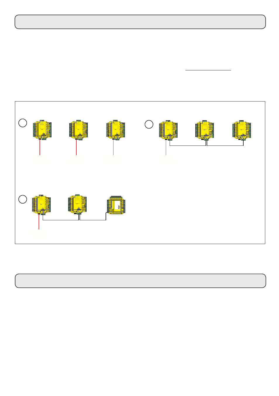
Here are three typical site layouts.
1 - The Net2 plus ACU's can be individually connected to
the Net2 PC via the site LAN network.
2 - The Net2 plus ACU's can be hardwired on a daisy
chain RS485 data line with ONE of them connected to
the Net2 PC via the site LAN network.
3 - The Net2 plus ACU can be used as the TCP/IP
converter for a line of Net2 plus and Net2 classic ACU's.
1
2
3
Each time the unit is powered on, it will run an internal health check. During this phase (about 5 secs) the OK
LED will flash quickly before changing to a slower heartbeat.
1
r
ed
ae
R
:
n
oi
t
ua
C
yl
no
s
re
da
er
C
D
V2
1
ro
F
2
r
ed
ae
R
12V
Red LED
Amber LED
Green LED
Data/D0
Clock/D1
Media Detect
0V
12V
Red LED
Amber LED
Green LED
Data/D0
Clock/D1
Media Detect
0V
N.C.
N.O.
COM
N.C.
N.O.
COM
Alarm
12V
Green LED
Exit
0V
st
up
nI
tputsu
O
re
o
0V
12V
Contact
0V
0V
amper
re
p
ma
/
tc
at
no
C
no
tt
u
ti
xE
2
yal
e
R
1
yal
e
R
Expansion
Rx
x
R
Net ork
CA
Cable Codin
nr
G/
t
e
ra
ps
r
o
ne
er
c
a
ta
d
mo
r
s
er
oc
el
ba
c
ne
er
G
nr
O/
t
e
na
r
O
10/100 Et ernet
er er Connected
er er Link 100
10
End o Line ermination
ON
OFF
Net2 plus
LACE ERIAL
N M ER
LA EL ERE
Intruder Alarm
et
V0
mr
A
es
ne
M
O
C
.
O.
N
Net2 plus
Remember, the Net2 plus is a combined TCP/IP interface and an Access Control unit. If the TCP/IP interface is
being used, you will need to detect the interface first using the procedure on the following pages.
This is important if you are replacing an existing Net2 plus. The Replace wizard in the Doors screen does NOT
reconfigure the IP address so it must be done manually. The wizard will then copy across the user data.