Signal balance error – NTi Audio Minilyzer ML1 User Manual
Page 32
32
Measurement Functions
signal balance error
The signal balance error reflects the deviation from the perfect
balance status. No signal balance error indicates that the absolute
levels at XLR-pin 2 and pin 3 relative to pin 1 (ground) are identical
and opposite in polarity.
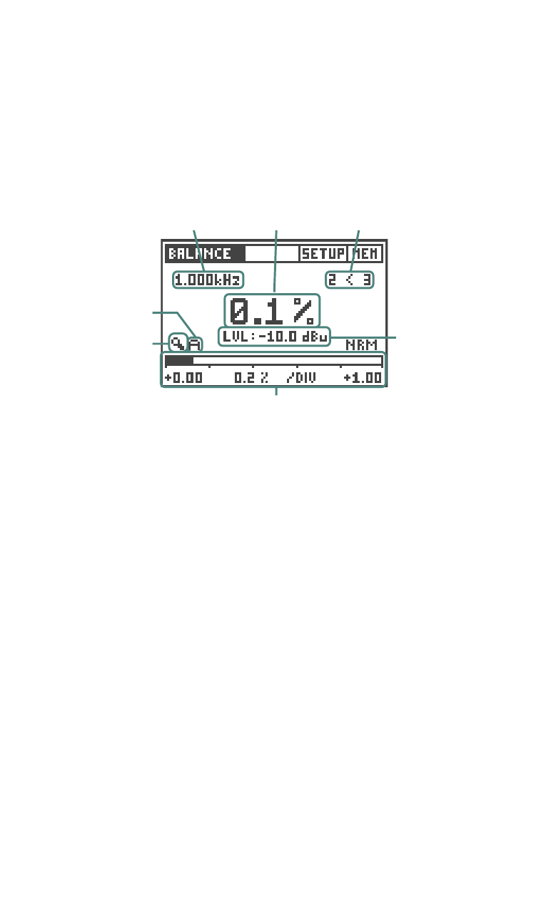
Fig 3.15 Signal Balance Error Screen
Frequency of
Input Signal
Balance Indicator
XLR-pin 2,3
Signal Balance
Error
Input
Level-RMS
Bargraph
Zoom
Control
Bargraph
Zoom Mode
Bargraph with Scaling Information
In the BALANCE mode, the signal balance error is shown in a numerical
value, which is the deviation from the optimum in percent.
balance Indicator: The direction of the deviation is indicated by the
arrows like 2 < 3 or 2 > 3, whereby the numbers 2 and 3 represent
the signal at XLR-pin 2 and pin 3.
In the Level, THD+N and Polarity (electrical input only) measurement
function, the Minilyzer permanently monitors the balance of the input
signal by a graphical indicator. This enables e.g. to check whether
cable connections are made correctly.
Bargraph: The bargraph shows an analog display of the signal
balance error. The scaling may be controlled automatically or
manually.
• Select manual (M) or automatic (A) scaling by the bargraph zoom
mode field.
• Within the manual scaling press the left/right keys to scroll through
the actual range or the up/down keys to increase or decrease the
range (sensitivity) of the bargraph scale.
• Press enter to confirm your setting.