Easurement, Unctions, Level rms – NTi Audio Minilyzer ML1 User Manual
Page 18: Measurement functions level rms
18
3. MeAsureMeNT fuNCTIoNs
Level RMS
LEVEL RMS reflects the absolute level of the line input signal.
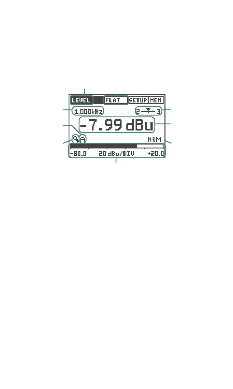
Fig 3.1 Level RMS Meter Panel
Display
Filter
Measurement
Function
Active
Filter
Frequency
Bargraph
Zoom
Mode
Bargraph
Zoom
Control
Signal
Balance
Level RMS
Result and
Unit
Bargraph with Scaling Information
To enter the LEVEL RMS mode, select LEVEL -> RMS in the
measurement functions submenu.
signal balance: This indicates the deviation from level-match of the
incoming balanced signal between pin 2 and pin 3 in percent (%).
The position of the arrow indicates the following:
• Arrow in center, the input signal is balanced.
• Arrow out of center, linear indication of a balancing problem, e.g.
arrow moves left nearer to the number 2 shows the signal level
on pin 2 is higher than on pin 3.
• Left or right end, the signal balance error is 33% or higher. 33%
equals a difference in the signal level of 6 dB.
• UNBAL, the signal balance symbol changes to UNBAL at the
signal balance error exceeding 90%.
result and unit: Level RMS. The units dBu, dBV, V are selectable.
Bargraph: The bargraph provides an analog display of the RMS level.
The scaling may be controlled automatically or manually.
• Select manual (M) or automatic (A) scaling by the bargraph zoom
mode field.
• Within the manual scaling (M) select the bargraph zoom control,
press enter and the left/right keys to scroll through the
Measurement Functions