Measuring functions, As well as in video frames, Audio signal clock signal not active – NTi Audio Digirator DR2 User Manual
Page 47
47
Measuring Functions
PAL / NTSC settings
The measured I/O delay time (latency) is displayed in millisec-
onds
1
as well as in video frames
2
. To alter between PAL
and NTSC settings, proceed as follows:
1. Navigate the cursor with the rotary wheel to the field dis-
playing NTSC or PAL
2
.
2. Press „ENTER“ to alter between time and video frames.
You have configured the units for the FRAME display.
Non-equal values for channel A and B
In case there is a non-equal delay value for channels A and B,
the instrument will display the two different respective values
in an alternating sequence. The channel display
3
follows the
actual displayed channel.
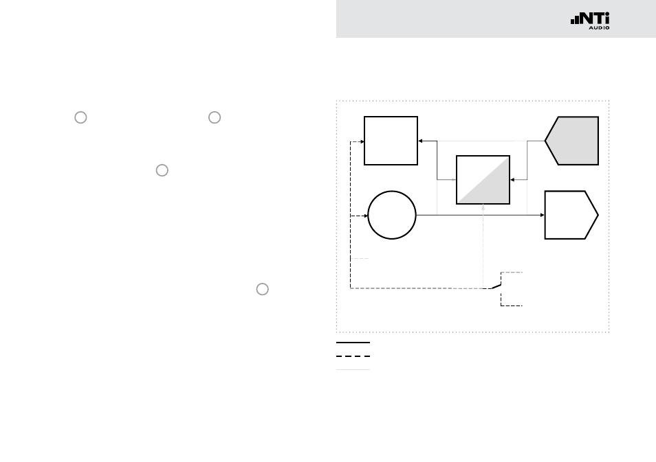
DR2 internal signal flow for the I/O Delay measurement
Digital Audio
Transmitter
Sample Rate
Converter
Digital Audio
Receiver
Signal
Generator
Analyzer
fs = 48 kHz
32.0 kHz
44.1 kHz (*2 , *4)
48.0 kHz (*2 , *4)
INT
EXT
Video (PAL, NTSC)
Word Clock
AES3, DARS
Digital Audio
Transmitter
Sample Rate
Converter
Digital Audio
Receiver
Signal
Generator
Analyzer
fs = 48 kHz
32.0 kHz
44.1 kHz (*2 , *4)
48.0 kHz
(*2 , *4)
INT
EXT
Video (PAL, NTSC)
Word Clock
AES3, DARS
Digital Audio
Transmitter
Sample Rate
Converter
Digital Audio
Receiver
Signal
Generator
Analyzer
fs = 48 kHz
32.0 kHz
44.1 kHz
(*2 , *4)
48.0 kHz
(*2 , *4)
INT
EXT
Video (PAL, NTSC)
Word Clock
AES3, DARS
Digital Audio
Transmitter
Sample Rate
Converter
Digital Audio
Receiver
Signal
Generator
Analyzer
fs = 48 kHz
32.0 kHz
44.1 kHz (*2 , *4)
48.0 kHz
(*2 , *4)
INT
EXT
Video (PAL, NTSC)
Word Clock
AES3, DARS
fs = 20 - 216 kHz
fs = 20 - 216 kHz
fs ≈ 32 - 48 kHz
fs = ~ 48 kHz
fs ≈ 48 kHz
Audio signal
Clock signal
not active