Measuring functions, Important, Audio signal clock signal not active – NTi Audio Digirator DR2 User Manual
Page 45
45
Measuring Functions
Important
An intermittent appearance of INPUT
IMPEDANCE and CLOCK SOURCE is a
strong indicator that the device or system
under test does not create its own clock,
but regenerates the input clock. To solve
this loop-back problem switch back to
CLOCK SOURCE INTERNAL.
Test procedure
For testing the transparency of a transmission channel you pro-
ceed as follows:
1. Connect the output of the DR2 to the input of the system
under test.
2. Connect the output of the system under test with the SYNC
input of the DR2.
3. Select the settings for clock source and termination.
The result of the continuously measured transparency anal-
ysis is displayed.
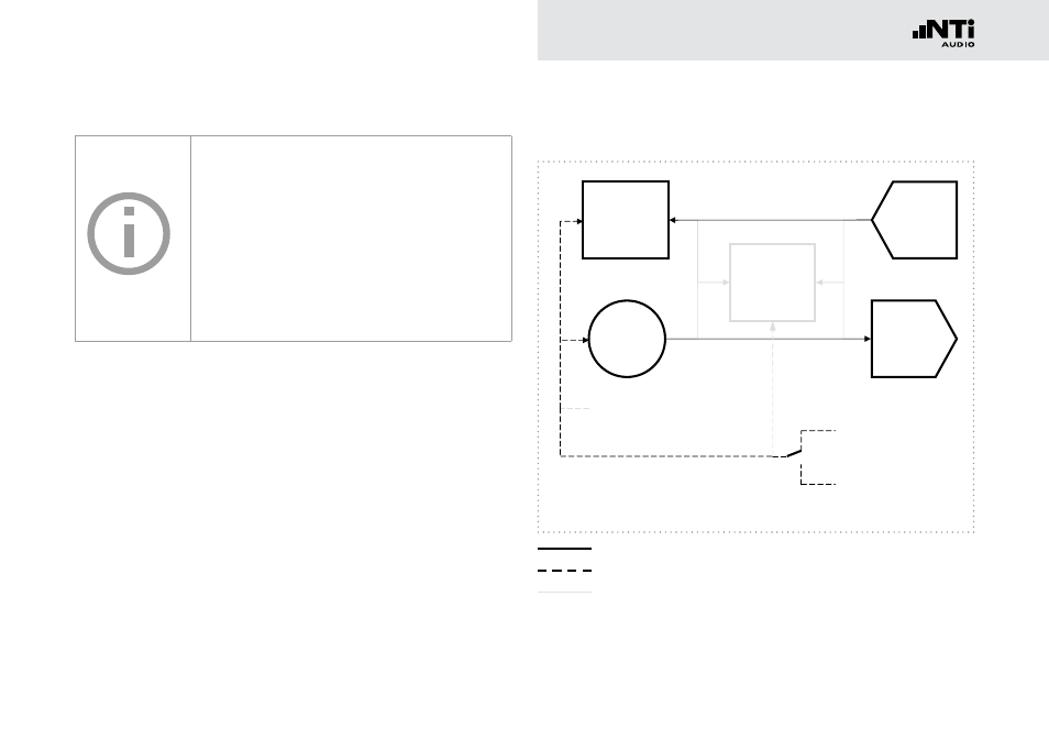
Signal flow during transparency test
Digital Audio
Transmitter
Sample Rate
Converter
Digital Audio
Receiver
Signal
Generator
Analyzer
fs = 48 kHz
32.0 kHz
44.1 kHz (*2 , *4)
48.0 kHz (*2 , *4)
INT
EXT
Video (PAL, NTSC)
Word Clock
AES3, DARS
Digital Audio
Transmitter
Sample Rate
Converter
Digital Audio
Receiver
Signal
Generator
Analyzer
fs = 48 kHz
32.0 kHz
44.1 kHz (*2 , *4)
48.0 kHz
(*2 , *4)
INT
EXT
Video (PAL, NTSC)
Word Clock
AES3, DARS
Digital Audio
Transmitter
Sample Rate
Converter
Digital Audio
Receiver
Signal
Generator
Analyzer
fs = 48 kHz
32.0 kHz
44.1 kHz
(*2 , *4)
48.0 kHz
(*2 , *4)
INT
EXT
Video (PAL, NTSC)
Word Clock
AES3, DARS
Digital Audio
Transmitter
Sample Rate
Converter
Digital Audio
Receiver
Signal
Generator
Analyzer
fs = 48 kHz
32.0 kHz
44.1 kHz (*2 , *4)
48.0 kHz
(*2 , *4)
INT
EXT
Video (PAL, NTSC)
Word Clock
AES3, DARS
fs = 20 - 216 kHz
fs = 20 - 216 kHz
fs ≈ 32 - 48 kHz
fs = ~ 48 kHz
fs ≈ 48 kHz
Audio signal
clock signal
not active