Engine control unit (ecu), Figure 4. engine control unit (ecu)/battery switch – Multiquip DCA300SSCU2_SSCU4i User Manual
Page 18
page 18 — dca300sscu2/4i 60 hz generator • operation and parts manual — rev. #1 (10/21/13)
eNGiNe CONtrOL UNit (eCU)
Figure 4. Engine Control Unit (ECU)/Battery Switch
PSI
OIL PRESS
0
25
50
75
100
°F
WATER TEMP
100
140
180
220
260
VOLTS
BATTERY
6
12
18
24
30
°F
FUEL
E
½
F
RPMX10
SPEED
0
120
150
180
210
60
Series 800 Controller
ECU
Engine Started
Shutdown
Pre-Alarm
Alarm
Acknowledge
Screen
Change
Program
Exit
Option
OFF
U-V
W-U
V-W
OFF
V
W
U
INCREASE
DECREASE
Series 800 Controller
ECU
Engine Started
Shutdown
Pre-Alarm
Alarm
Acknowledge
Screen
Change
Program
Exit
Option
A
B
C
D
E
F G
H
1
OFF
ON
2
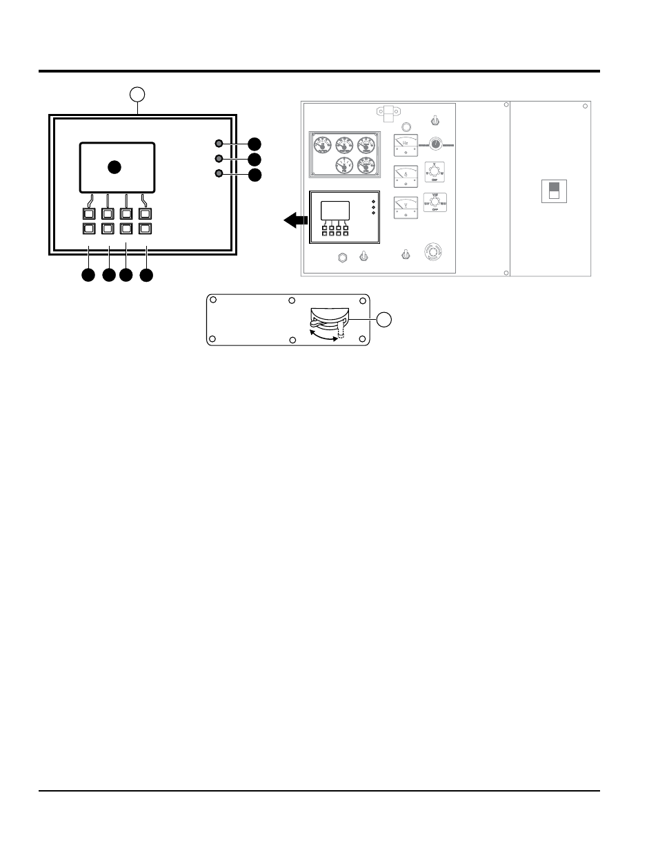
The definitions below describe the controls and functions
of the Engine Control Unit (Figure 4).
1.
ecu controller — This auto start/stop controller
displays the parameters and the diagnostic
troubleshooting messages of the engine, and controls
DPF regeneration.
A.
ecu display screen — Engine fault diagnostic
messages are shown on this LCD display. screen
B.
engine started lamp — This lamp when lit
indicates engine is operating normally.
C.
engine shutdown lamp — When an engine
failure has occured this lamp will blink. Indicating
the engine has been shutdown. The diagnostic
fault message will be displayed on the LCD screen.
D.
pre alarm lamp — When an engine failure has
occured this lamp will blink. Indicating a pre-fault
engine condition and the possibility of engine
shutdown.The diagnostic fault message will be
displayed on the LCD screen
E.
alarm acknowledge Button — When the engine
experiences a fault, the "Pre Alarm Lamp" or the
"Shutdown Lamp" will start blinking. Pushing this
button will confirm the fault message and the
blinking lamp will change to a solid lamp display.
The fault message will be displayed on the screen.
When multiple engine faults occur, the lamp will
continue blnking until all fault messages are
confirmed. The blinking lamp will change to a solid
lamp display all current confirmed fault messages
will scrool across the screen.
F.
screen change Button — When this button is
pushed during operation, the screen will cycle
through each parameter screen.
G.
option Button — This button is not active. Do
not use.
H.
program/exit Button — Pushing this button
allows the DPF Force Regen and diagnostic code
to be confirmed.
2.
Battery switch — This switch should be set to the ON
position during normal operation. After the engine has
been stopped, wait 30 seconds before placing switch in
the
OFF position. Changing the position of the switch
(ON to OFF) during normal operation could cause
damage to generator's electrical components.