Maintenance – Multiquip JTNSW20HTCSL User Manual
Page 29
JTNS20H/SW20H-SeRIeS RIDe-ON pOWeR TROWeL • OpeRaTION maNuaL — Rev. #4 (10/15/13) — page 29
SpaRe DRIve BeLT RemOvaL
(uSINg RepLaCemeNT DRIve BeLT)
The MQSJTN20-Series Ride-On Power Trowel is equipped
with two replacement (spare) drive belts, which are
mounted inside the drive belt guard.
aLWaYS make sure
that there are two spare drive belts installed inside the
drive belt guard before the trowel is placed onto a slab to
finish concrete.
In the event of a drive belt failure, the replacement (spare)
drive belts can be used for quick replacement at the job
site for continued trowel operation.
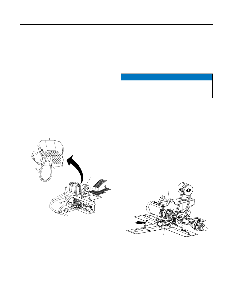
1. To replace the existing drive belts with the spare drive
belts, remove the 3 bolts (Figure 21) that secure the
drive belt guard to the frame.
2. Position the drive belt guard in a maner to gain access
to the spare belt holder.
3. Remove the nut and flat washer (Figure 23) that secure
the spare belt holder to the to the drive belt guard.
Figure 23. Spare Belt Removal
4. Lift spare belt holder and free drive belts.
5. Take care not to contaminate the replacement drive
belts with grease or dirt.
6. Remove existing drive belt from clutch and lower drive
pulley, by cutting belt.
BATTERY
CLUTCH
ENGINE
MOUNTING
BOLTS (4)
SPARE BELT
HOLDER
REMOVE
NUT AND
FLAT WASHER (2)
SPARE
V-BELTS (2)
DRIVE BELT
GUARD
7. Ensure all remnants of old drive belt have been
removed from the sheaves/grooves of the clutch and
lower pulley.
8. Next loosen the four engine mounting bolts and slide
the engine toward the rear of the trowel. Slide the first
belt over the clutch and place it on the upper drive
pulley, then pull it down and place it on the lower drive
pulley. Repeat this procedure for the second belt.
SpaRe DRIve BeLT INSTaLLaTION
Cv-joint assembly Removal (Left-Side)
After the replacement (spare) belts have been installed onto
the clutch and lower pulley, it will be necessary to install
a new set of spare drive belts onto the spare belt holder.
Perform the procedure shown below to install new drive
belts back onto the spare belt holder:
1. If necessary, place the trowel on suitable supports
(jack-stands) and observe all safety precautions.
2. Starting at the left-side gearbox, use a 1/4" allen
wrench and remove the 3 bolts and lock washers that
secure the CV-joint (Figure 24) to the left-side gearbox.
Retain mounting hardware for later use.
Figure 24. Disconnecting CV-Joint
NOTICE
To reinstall a new set of spare V-belts onto the spare
belt carrier, it will be necessary to disassemble the
CV-joint from the left-side gearbox coupler.
LEFT
REAR
REMOVE
BOLT (3)
CV-JOINT
maintenance