Ti front panel, Ti front panel 34 – MTS SWIFT 40 Sensor User Manual
Page 34
SWIFT 40 Sensors
34
Transducer Interface
Hardware Overview
TI Front Panel
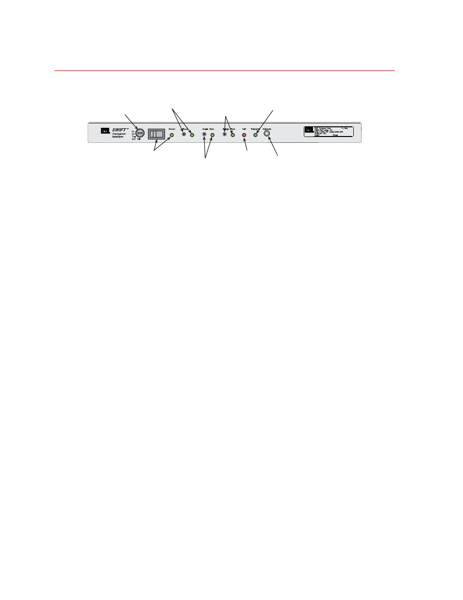
Transducer Interface Front Panel
Fuse (F1)
A 3A fuse protects the electronics.
Power switch and
Indicator
The power switch turns power on and off. A green indicator will light to indicate
that the TI power is turned on.
Shunt switch
Pressing this switch performs a shunt calibration (shunt cal) of the transducer.
You do not need to hold the switch in continuously, only until the Shunt indicator
lights up (indicating that the TI has started the shunt cal).
Before you perform a shunt cal, check that the appropriate shunt reference value
and error tolerance have been downloaded (these values are normally loaded
during system calibration, and are referred to as the shunt delta cal values).
A shunt calibration will determine the current delta values by measuring the
bridges unshunted and shunted, and then compare these values to the previously
loaded calibration values. If the measured values are outside of an acceptable
tolerance, the Shunt indicator will flash, indicating an error.
Shunt Indicator
This indicator indicates the current state of the shunts. If there are any active
shunts, or if you are currently performing a shunt calibration, this indicator will
be lit.
If the shunt cal check fails, this indicator flashes (at approximately a 1 Hz rate).
Note
The state of the shunt cal check is cleared at power-up, so the shunt cal
should be performed when the system installation is in question.
S20-11
Fuse
Power Switch
and Indicator
Shunt Switch
and Indicator
Angle Zero
Switch and Indicator
Bridge Zero
Switch and Indicator
Fail
Indicator
Transmit
Indicator
Address
Selector